Analyzer, lid device, and reagent storing device
- Summary
- Abstract
- Description
- Claims
- Application Information
AI Technical Summary
Benefits of technology
Problems solved by technology
Method used
Image

Examples
first embodiment
[0074] The first embodiment of the invention will be explained using FIGS. 1 to 7.
[0075] (Constitution of an Analyzer)
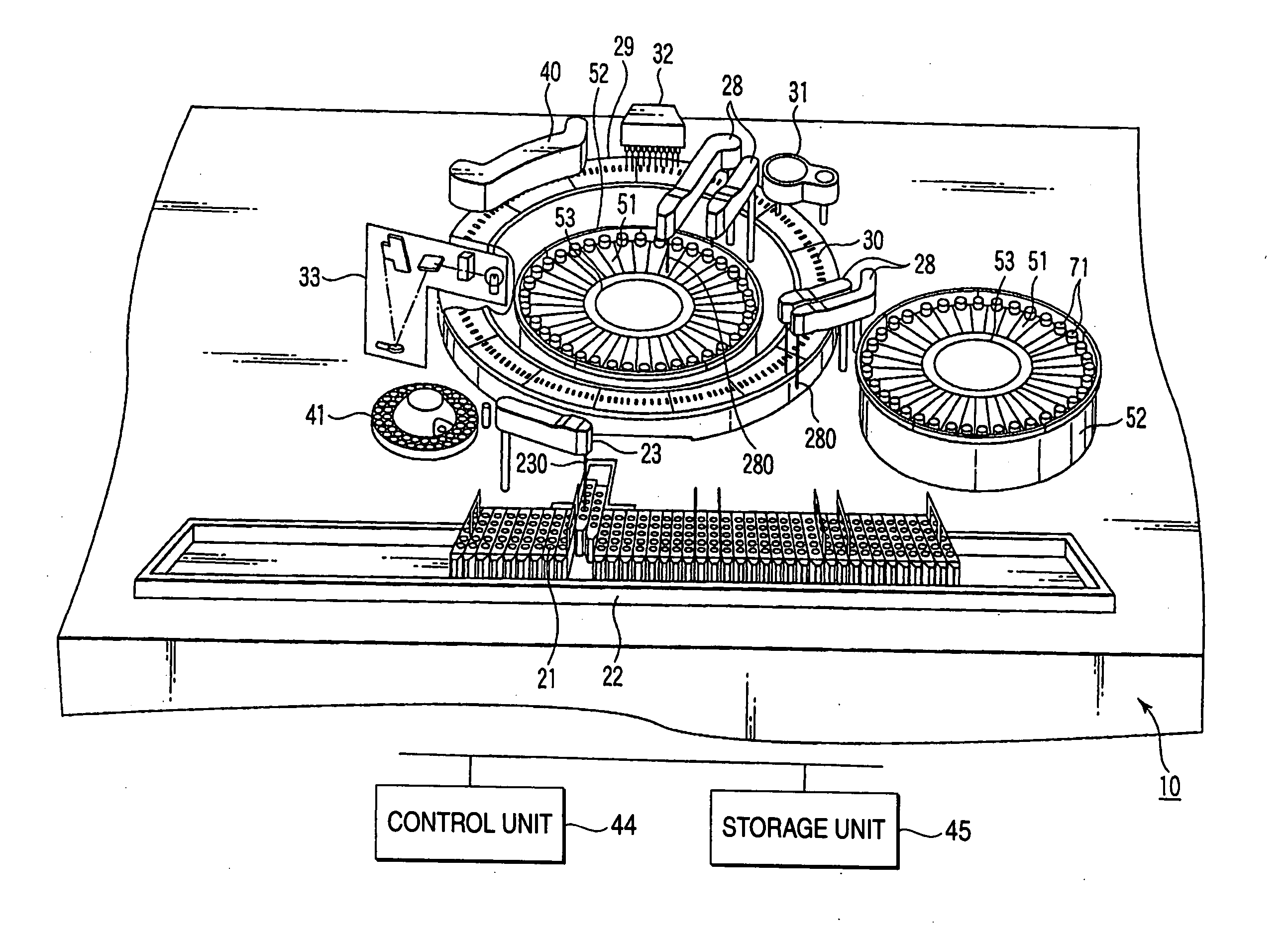
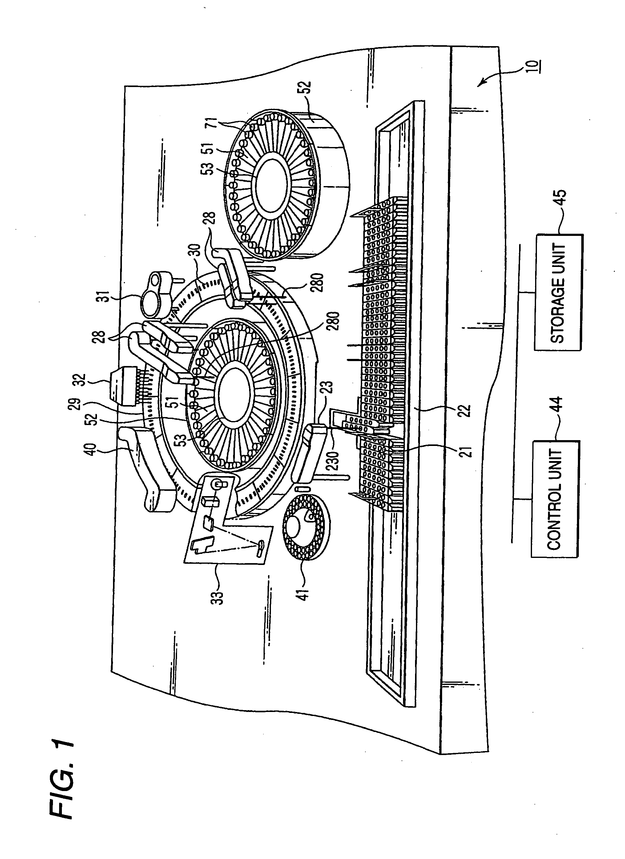
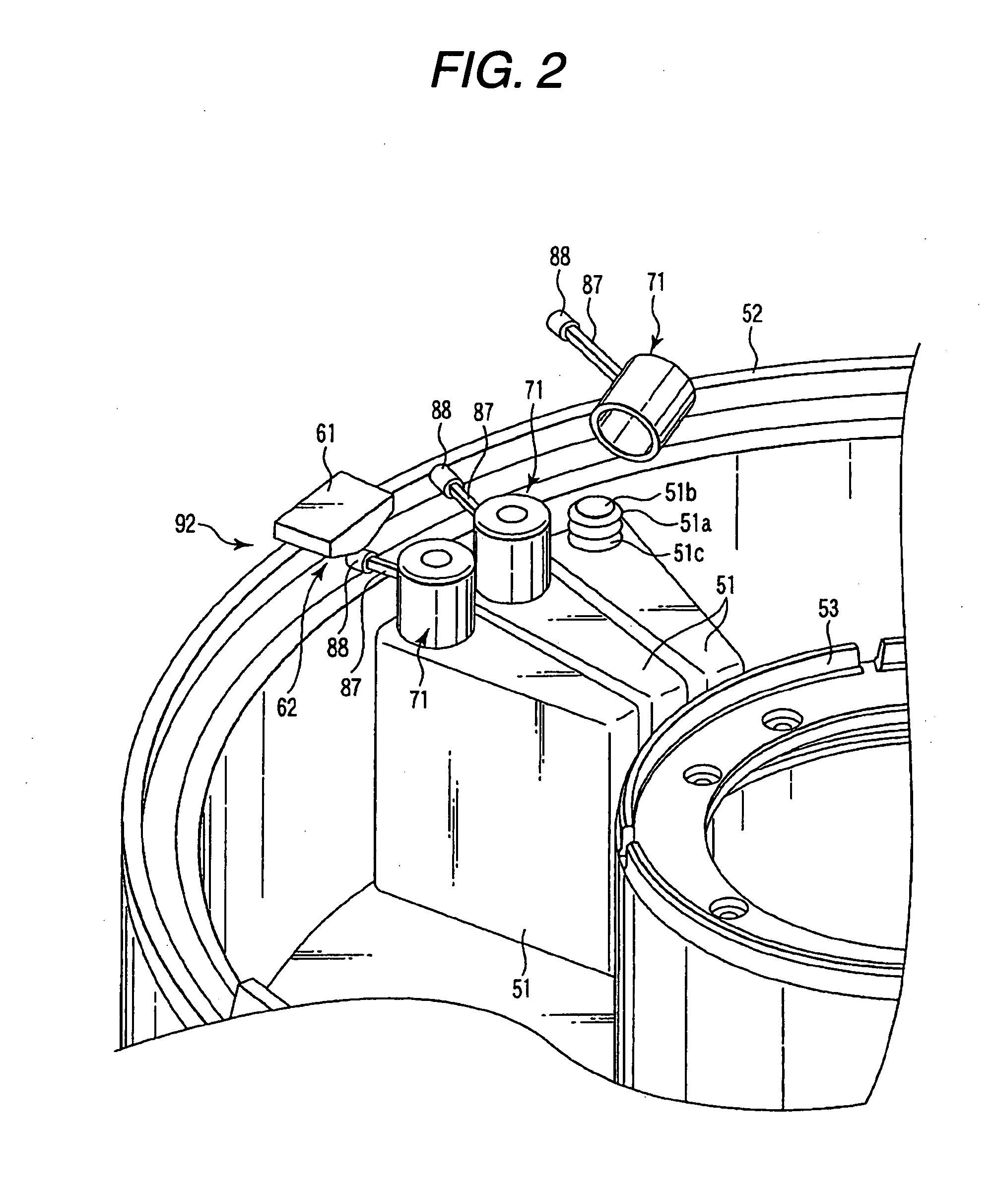
[0076]FIG. 1 is a schematic perspective view of an analyzer according to the first embodiment of the invention. FIG. 2 is a perspective view of a reagent storage according to the embodiment.
[0077] As shown in FIGS. 1 and 2, this analyzer includes an apparatus body 10, sample containers 21, a pedestal 22, a sample dispensing arm 23, reagent containers 51, a reagent storage 52, a container shelf 53 a reagent dispensing arm 28, a reaction disk 29, reaction tubes 30, an electrode unit 31, a cleaning unit 32, a measuring unit 33, an agitating unit 40, a sample container 41, a control unit 44, a storage unit 45, an opening / closing block 61, and lid members 71.
[0078] The components will be explained.
[0079] The sample containers 21 store samples such as a serum of a human body.
[0080] The pedestal 22 supports the plural sample containers 21 and moves the sample containe...
second embodiment
[0131] Next, a second embodiment of the invention will be explained using FIGS. 8 to 11. Components same as those in the embodiment described above are denoted by the same reference numerals and signs and explanations of the components are omitted.
[0132]FIG. 8 is a schematic plan view of a lid member 71a and the opening / closing block 61 according to the second embodiment of the invention. FIG. 9 is a cross sectional view of the lid member 71a and the opening / closing block 61 at the time when an inner lid 83a according to this embodiment is in the closing position. FIG. 10 is a cross sectional view of the lid member 71a and the opening / closing block 61 at the time when the inner lid 83a according to this embodiment is in the opening position. FIG. 11 is a schematic perspective view of the swing arm 87 and the inner lid 83a according to this embodiment.
[0133] As shown in FIGS. 8 to 11, the lid member 71a according to this embodiment has, on a surface of the swing arm 87 opposed to t...
third embodiment
[0138] A third embodiment of the invention will be explained using FIGS. 12 to 14. Components same as those in the embodiments described above are denoted by the same reference numerals and signs and explanations of the components are omitted.
[0139]FIG. 12 is a schematic plan view of a lid member 71b and the opening / closing block 61 according to the third embodiment of the invention. FIG. 13 is a cross sectional view of the lid member 71b and the opening / closing block 61 at the time when an inner lid 83b according to this embodiment is in the closing position. FIG. 14 is a cross sectional view of the lid member 71b and the opening / closing block 61 at the time when the inner lid 83b according to this embodiment is in the opening position.
[0140] As shown in FIGS. 12 to 14, the lid member 71b according to this embodiment includes an insertion opening 99 in a position of the peripheral wall 72b of the outer lid 72 on the opposite side of the peripheral opening 79. A support section 84...
PUM
 Abstract
Description
Claims
Application Information
 - R&D Engineer
- R&D Manager
- IP Professional
- Industry Leading Data Capabilities
- Powerful AI technology
- Patent DNA Extraction
Browse by: Latest US Patents, China's latest patents, Technical Efficacy Thesaurus, Application Domain, Technology Topic.
© 2024 PatSnap. All rights reserved.Legal|Privacy policy|Modern Slavery Act Transparency Statement|Sitemap