

Low noise amplifier for electro-physiological signal sensing
a low-noise, amplifier technology, applied in the field of diagnostic testing, can solve the problems of amplifiers being prone to saturation and non-linear response, use of hospital-grade isolation transformers, and low amplitude of electrically measured neural response signals derived from such procedures, and achieve accurate amplifying of neural response signals. , the effect of low nois
Inactive Publication Date: 2006-06-08
LKC TECH
View PDF3 Cites 68 Cited by
- Summary
- Abstract
- Description
- Claims
- Application Information
AI Technical Summary
Benefits of technology
[0022] Accordingly, it is a primary object of the present invention to overcome the above mentioned difficulties by providing a r
Problems solved by technology
Electrically measured neural response signals derived from such procedures are very low in amplitude and are susceptible to corruption in noise.
In prior art diagnostic instruments, this mandated the use of hospital grade isolation transformers, which are bulky, expensive and prone to introducing electrical noise artifacts in an electrically measured neural response signal.
Otherwise, the amplifiers would be prone to saturation and non-linear response.
The prior art practice of omitting the electrically measured neural response signal's slowly varying Direct Current (DC) offset component may be the primary cause for a lack of basic science tending to promote understanding of slowly varying neural responses.
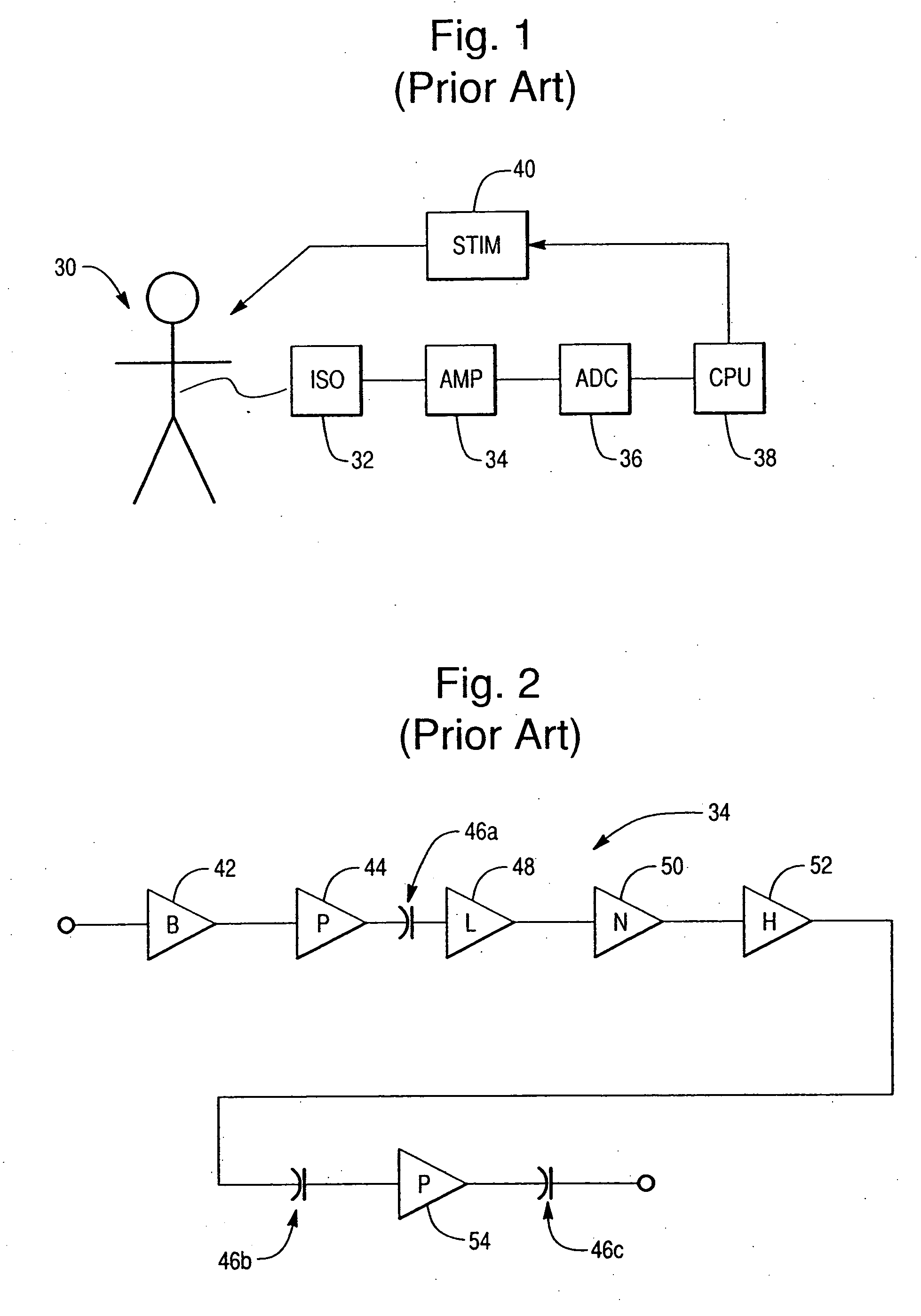
Prior art amplifier circuits such as that shown in FIGS. 1 and 2 have not been entirely satisfactory for every neural testing application, however, because they are not sensitive enough to detect many weak electrical signals.
Each amplification stage and the electrical connections between the stages contribute to background noise tending to corrupt the electrically measured neural response signal.
The noise specifications for the prior art amplifiers adapted for use in diagnostic instruments have traditionally been less than three microvolts (3 μV), and so the smaller signals (e.g., 1-3 microvolts) are lost in the amplifier's noise and remain unavailable for analysis or display.
However, the AC components, especially the lower frequency AC components, are not always suitable.
If the AC/DC separation frequency is set too low (e.g., close to 0.001 Hz or even lower), any large transient input fluctuation due to spurious
Method used
View moreImage
Smart ImageViewing Examples


Examples
 PUM
 Abstract
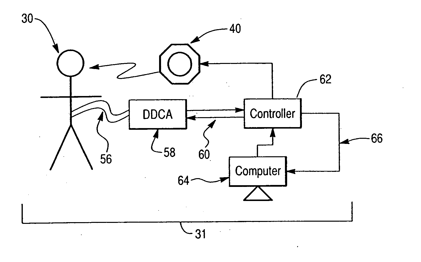
A reliable, safe, accurate, low noise, inexpensive, portable amplifier circuit is adapted to accurately amplify both AC and DC neural response signals. A patient or subject is electrically connected to a multi-channel system for electrically measuring the patient's AC and DC neural response signals at a plurality of locations using electrodes connected through a multi-electrode cable. The neural response signals are input to a digital DC amplifier to filter, amplify and digitize the neural response signals. Digitized neural response signals are converted to optical signals and transmitted via a fiber optic cable to an interface that is preferably connected to a patient stimulus generator (e.g., a Ganzfeld stimulator or pattern stimulator for multi-focal ERG). The system also includes a stand-alone computer such as an IBM® compatible Personal Computer (PC) for two-way communication with the interface via a standard data interface cable (e.g., a USB cable). In the preferred embodiment, a digital DC amplifier is worn by the patient and receives each neural response signal at a two-conductor balanced input; a surge suppression circuit limits excessive voltage transients at the input. The neural response signal is next input to a balanced buffer amplifier stage for impedance matching and the buffered neural response signal is then input to a balanced, adjustable pre-amplifier stage having an adjustable gain which can be varied (e.g., from ×1 to ×64). The buffered, amplified neural response signal is then digitized for storage in a memory and transmission to a fiber-optic digital transmission circuit. An adjustable impedance element generates a DC offset compensation signal used to control a D.C. offset compensation amplifier to generate an offset control signal for input to gain-adjustable pre-amplifier stage, to maximize sensitivity and usable dynamic range.
Description
[0001] A computer program listing appendix is submitted herewith on compact disc recordable (CD-R) as Appendix A. Duplicate copies of Appendix A are provided as Copy 1 and Copy 2. The materials on the CD-R are identical to each other. [0002] The files on the compact discs are incorporated herein by reference, and are listed below: File NameSize in bytesDateC_code_DCamp.txt50.4 KbOct. 29, 2003C_code_Interface.txt35.8 KbOct. 29, 2003BACKGROUND OF THE INVENTION [0003] 1. Field of the Invention [0004] This invention relates generally to instruments for use in diagnosis and assessment of medical disorders by objective means. More specifically, it relates to diagnostic testing and, more particularly, to diagnostic testing of the nervous system. In humans, such testing is often done in conjunction with diagnostic procedures such as electro-retinography (ERG) and multi-focal ERG. [0005] 2. Discussion of the Prior Art [0006] ERG provides for the determination of extent and magnitude of loca...
Claims
Login to View More Application Information
Patent Timeline
 IPC IPC(8): A61B5/04
CPCA61B5/0017A61B5/04004A61B5/0484H03F3/45H03F3/45973H03F2200/331A61B5/30A61B5/377
InventorTSAU, YANG
OwnerLKC TECH