Various apparatus and methods for deep brain stimulating electrodes

a technology of electrodes and deep brain, applied in the field of deep brain stimulating probes, can solve the problem of not being able to capture the target within the available footprin

Inactive Publication Date: 2006-06-08
VARDIMAN ARNOLD B
View PDF8 Cites 57 Cited by
  • Summary
  • Abstract
  • Description
  • Claims
  • Application Information

AI Technical Summary

Benefits of technology

[0025] These and other embodiments will be more fully appreciated from the description below.

Problems solved by technology

If the initial surgical placement of the electrode in the brain is sufficiently “off-target,” it is impossible to capture the target within the available “footprint” of the electrical field generated by the electrodes of the currently available deep brain stimulating devices.

Method used


Image

  • Various apparatus and methods for deep brain stimulating electrodes
  • Various apparatus and methods for deep brain stimulating electrodes
  • Various apparatus and methods for deep brain stimulating electrodes

Examples


Embodiment Construction

[0070] Corresponding reference numbers indicate corresponding parts throughout the several views of the drawings and specification.

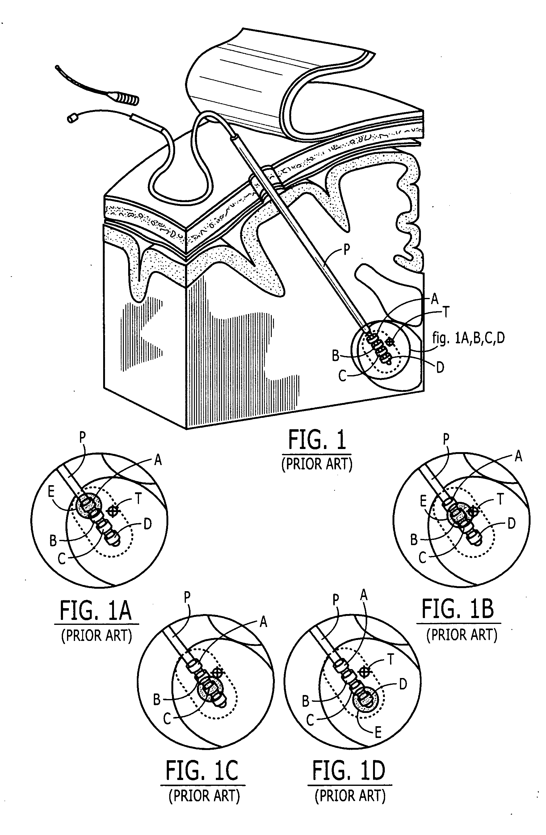
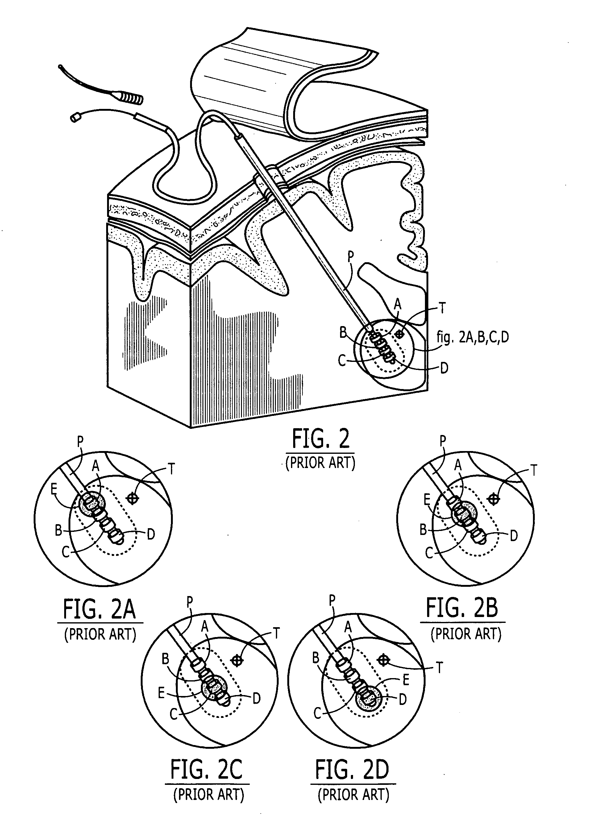
[0071] A variety of disabling diseases affecting the central nervous system have proven responsive to treatment using electrical stimulation of specific anatomic targets T. As such, it is desirable for the electrical field E of stimulating probe P, seen as a shaded area E and also known as an electrical “footprint,” to reach the targeted portion T of the human brain, as seen in FIG. 1B.

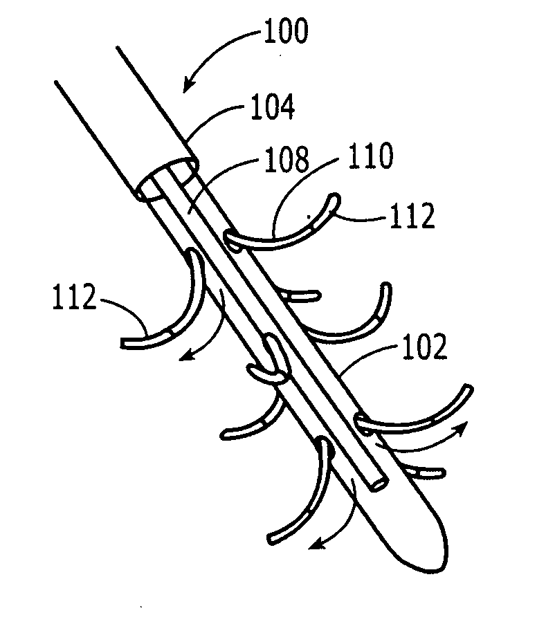
[0072]FIG. 1 illustrates a currently available deep brain stimulation electrode probe P with four electrodes (A, B, C and D) arranged as narrowly spaced bands on the terminal end of a stimulating probe P. The physiologic effect of the stimulation of probe P can be modulated by altering which electrode (A, B, C or D) is energized or by altering the amplitude, frequency or pulse width of the electrical current. However, the four-banded electrodes seen in FIG. 1 are in fixe...


PUM


Abstract

A deploying deep brain stimulating probe with a shaft, at least one opening on said shaft, at least one extendable tendril, said tendril deploying from said shaft into surrounding tissue through said opening and an electrode disposed on said tendril.

Description

RELATED APPLICATION [0001] This application claims priority from U.S. Provisional Patent Application Ser. No. 60 / 620,905, filed Oct. 21, 2004 and entitled Various Apparatus and Methods for Deep Brain Stimulating Electrodes.TECHNICAL FIELD OF THE INVENTION [0002] The technical field of the invention relates to deep brain stimulating probes, such as electrodes. [0003] The technical field of the invention relates to delivering infusates, with medicinal properties, into the brain. [0004] The present invention relates to a multi-directional synchronous deploying deep brain stimulating electrodes. [0005] The technical field of the invention relates to a multi-directional selectively deployable deep brain stimulating electrodes. [0006] The present invention relates to a large diameter deep brain stimulating electrodes. [0007] The present invention relates to a curved guide for anatomic arc placement of deep brain stimulating electrode. [0008] The present invention relates to apparatus for ...

Claims


Application Information

Patent Timeline
Patent Type & Authority Applications(United States)
IPC IPC(8): A61N1/05
CPCA61N1/0534A61N1/0539A61M2205/054A61M2210/0693A61M5/142A61N1/36067A61N1/36082
Inventor VARDIMAN, ARNOLD B.
Owner VARDIMAN ARNOLD B
Why Eureka
Try Eureka