Lifting cushion and method for transferring a patient from a chair

a technology for transferring patients and mattresses, applied in the field of apparatus and methods for moving people, can solve problems such as a lack of adequate patient transfer devices, patients and nurses continue to suffer from a lack of prior art devices, and injuries affecting patients and nurses

Active Publication Date: 2006-06-15
D T DAVIS ENTERPRISES LTD D B A HOVERTECH INT
View PDF14 Cites 11 Cited by
  • Summary
  • Abstract
  • Description
  • Claims
  • Application Information

AI Technical Summary

Problems solved by technology

Significantly, lifting a patient from a wheelchair to a bed or a bed to a wheelchair is one of the major causes of work-related injuries among nurses.
Therefore, regardless of existing transfer devices, patients and nurses continue to suffer from a lack of adequate patient transfer devices.
However, these prior art devices suffer from a number of disadvantages.
Thus, existing patient transfer devices are not being used as often as they should be to avoid injuries to hospital workers and to patients.
This device was adapted to engage both ceiling and floor, which is often not practical for use in hospitals or the nursing home environment.
Although it can raise, lower and carry the patient, using a hoist mounted to the ceiling, it takes up significant space and is time consuming to operate.
Moreover, it requires two separate pieces of equipment and may be expensive to maintain.

Method used


Image

  • Lifting cushion and method for transferring a patient from a chair
  • Lifting cushion and method for transferring a patient from a chair
  • Lifting cushion and method for transferring a patient from a chair

Examples


Embodiment Construction

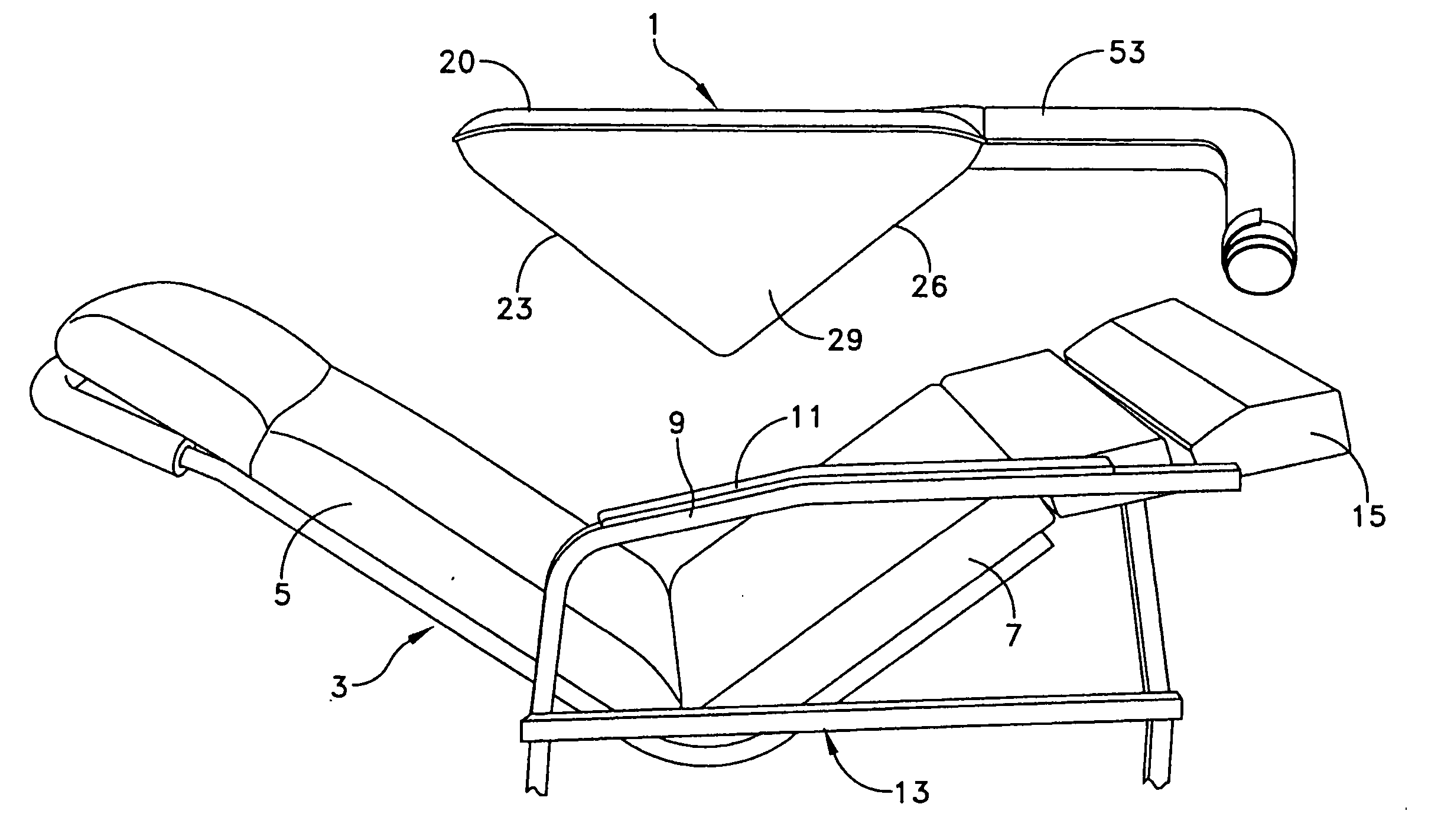
[0032] This description of preferred embodiments is intended to be read in connection with the accompanying drawings, which are to be considered part of the entire written description of this invention. The drawing figures are not necessarily to scale and certain features of the invention may be shown exaggerated in scale or in somewhat schematic form in the interest of clarity and conciseness. In the description, relative terms such as “horizontal,”“vertical,”“up,”“down,”“top” and “bottom” as well as derivatives thereof (e.g., “horizontally,”“downwardly,”“upwardly,” etc.) should be construed to refer to the orientation as then described or as shown in the drawing figure under discussion. These relative terms are for convenience of description and normally are not intended to require a particular orientation. Terms including “inwardly” versus “outwardly,”“longitudinal” versus “lateral” and the like are to be interpreted relative to one another or relative to an axis of elongation, o...


PUM


Abstract

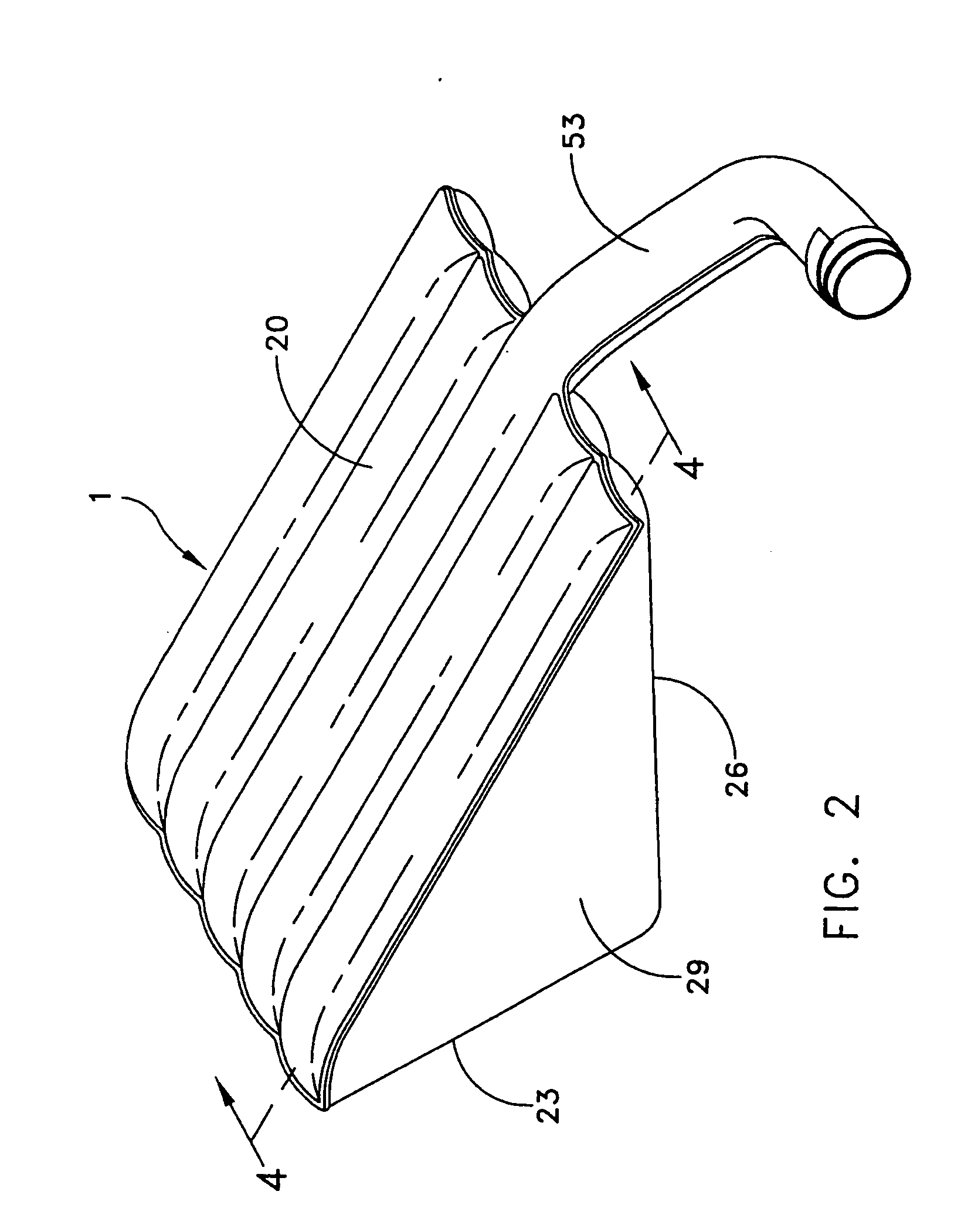
An inflatable lifting cushion for an articulated chair including a five-sided polygon capable that is longitudinally aligned on the seat and back of the chair. The cushion includes triangular side walls and at least one interior plenum having an air inlet port enabling air to enter and exit the plenum. A system for transferring a patient is provided including an articulated chair having a back and seat that are arranged to cooperate with one another for movement between an upright position and a reclining position. An inflatable lifting cushion is longitudinally positioned upon the back and the seat of the articulated chair. The inflatable lifting cushion comprises a five-sided polygon including triangular side walls and at least one interior plenum having an air inlet port enabling air to enter and exit the plenum. Another a system for transferring a patient is provided that includes an articulated chair having a back and seat that are arranged to cooperate with one another for movement between an upright position and a reclining position. An inflatable lifting cushion is longitudinally positioned upon the back and the seat of the articulated chair. The inflatable lifting cushion comprises a five-sided polygon including triangular side walls and at least one interior plenum having an air inlet port enabling air to enter and exit the plenum. A transfer mattress is positioned upon the lifting cushion for movement of a patient onto an adjacent bed.

Description

FIELD OF THE INVENTION [0001] The present invention generally relates to apparatus and methods for moving people and, more particularly, to apparatus and methods for moving a patient from a chair to a bed and vice-a-versa. BACKGROUND OF THE INVENTION [0002] Periodic patient transfers are required to provide the necessary care for patients that are disabled or who need total care due to paralysis, old age, fracture, comatose condition, post-surgery or other conditions which limit the patient's mobility. Regardless of existing patient transfer devices, nurses in hospitals and long-term care facilities are still manually lifting the patient in and out of bed several times during an eight-hour shift in order to provide proper and necessary patient care. The common practice among nurses for transferring patients between a chair and a bed requires two or more nurses to lift a patient upwardly from a sitting position in a chair and transfer them into a hospital bed. Significantly, lifting ...

Claims


Application Information

Patent Timeline
Patent Type & Authority Applications(United States)
IPC IPC(8): A61G5/14
CPCA61G7/1021A61G7/103A61G7/1036A61G2200/32A61G7/1028
Inventor DAVIS, DAVID T.
Owner D T DAVIS ENTERPRISES LTD D B A HOVERTECH INT
Why Eureka
Try Eureka