Derailment protection apparatus

Inactive Publication Date: 2006-06-15
HACHIKAWA MASATO
View PDF7 Cites 18 Cited by
  • Summary
  • Abstract
  • Description
  • Claims
  • Application Information

AI Technical Summary

Benefits of technology

[0016] The derailment protection apparatus of the present invention may return a wheel of a rolling stock to be deviated from a rai

Problems solved by technology

During the rolling stock runs on a track with curved rails, the retaining metals and the receiving metals always hit together because the rolling stock receives a large lateral vibration.
Therefore, this derailment preventing device can not used in general

Method used


Image

  • Derailment protection apparatus
  • Derailment protection apparatus
  • Derailment protection apparatus

Examples


first embodiment

the Invention

[0099] Referring to FIG. 1 through FIG. 15, the first embodiment of the invention is described in detail.

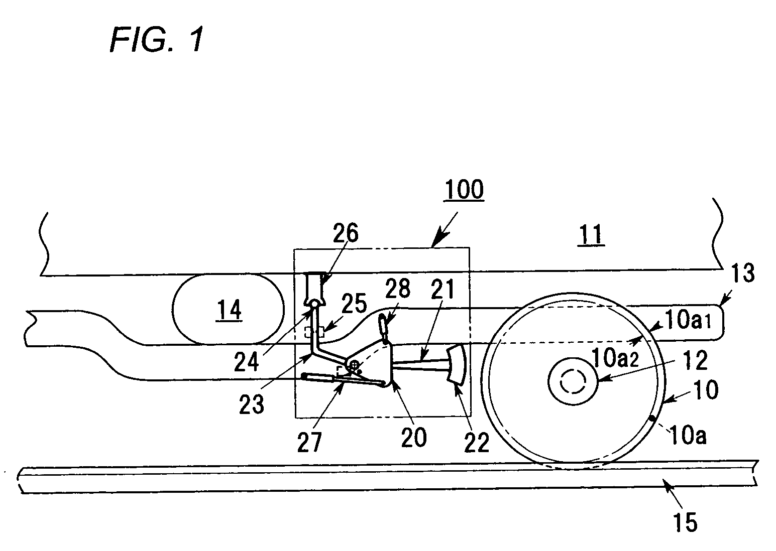
[0100]FIG. 1 is a schematic elevational view showing a relation between a derail protection apparatus 100 of the first embodiment and a rolling stock.

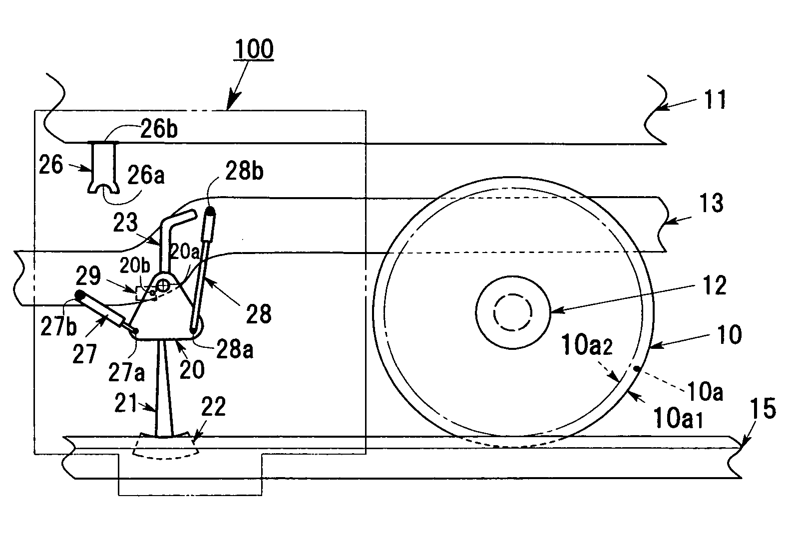
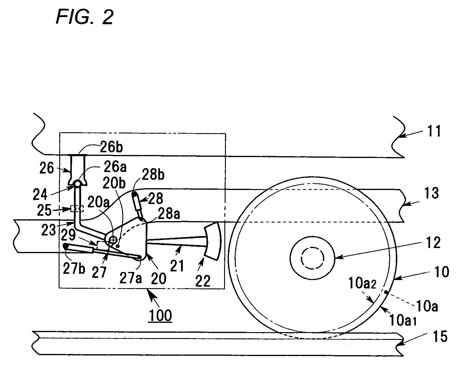
[0101]FIG. 2 is a schematic enlarged elevational view showing the derail protection apparatus 100.

[0102]FIG. 3 is a schematic enlarged elevational view showing the derail protection apparatus 100 in condition to activate operating.

[0103]FIG. 4 is a schematic enlarged elevational view showing a relation between the derail protection apparatus 100 and a bogie, when a derailed wheel is guided to return in a normal or original position on actuation of the derail protection apparatus 100.

[0104]FIG. 5 is a schematic enlarged cross sectional view showing one kind of shock sensors (an abnormal vibration responsive device) 24, 25 and 26.

[0105]FIG. 6 is a schematic enlarged cross sectional view showing another kind of shock...

second embodiment

the Invention

[0224] A derailment protection apparatus according to a second embodiment of the invention is explained referring to FIG. 16, FIG. 17, FIG. 18A and FIG. 18B.

[0225]FIG. 16 is a schematic elevational view of the derailment protection apparatus 200 according to the second embodiment of the invention.

[0226]FIG. 17 is a schematic enlarged elevational view in which major portions in FIG. 16 are partially drawn as a cross sectional view.

[0227]FIG. 18A and FIG. 18B are schematic enlarged elevational views to show a lock device and a neighborhood of the lock device shown in FIG. 17.

[0228]FIG. 18A shows a normal unlocked state of the lock device and FIG. 18B shows a locked state of the lock device, in which the derailment protection apparatus 200 starts to operate the lock device.

[0229] In the following explanation of the derailment protection apparatus 200 according to a second embodiment of the invention, the explanation duplicated with the first embodiment may be omitted ...

third embodiment

the Invention

[0259] Referring to FIG. 19, FIG. 20 and FIG. 21, the third embodiment of the present invention are explained as follows.

[0260]FIG. 19 is a schematic elevational view of the derailment protection apparatus 300 according to the third embodiment of the present invention.

[0261] As shown in FIG. 19, a derailment protection apparatus 300 may be composed of a locking / releasing device 60 and a lifting device 53 and 54 in addition to the derailment protection apparatus similar to the derailment protection apparatus 200.

[0262] In an explanation referring to FIG. 19, the explanation regarding to the same (common) elements denoted as the same reference numerals as FIG. 17 is as much as omitted. Therefore, please refer to the before-mentioned explanation referring to FIG. 17 regarding such common elements.

[0263] The high pressure gas valve 33′ may be provided with a cylinder 33a, a movable shaft 33b positioned within the cylinder 33a having a disk positioned at one end of the m...


PUM


Abstract

The disclosed is a derailment protection apparatus that may comprise a wheel guiding member or a rail contact member having an inclined surface, a descending device to descend the wheel guiding member or the rail contact member, and wherein the inclined surface comes in contact with a rail, when the descending device operates. The derailment protection apparatus may return a wheel of a rolling stock to be deviated from a rail to a normal position, when the rolling stock with a bogie receives an abnormal vibration due to such as earthquake.

Description

CROSS-REFERENCE TO RELATED APPLICATIONS [0001] This application claims the benefit of the prior foreign application: Japanese Patent Application No. 2004-382539 filed on Dec. 14, 2004 in the Japan Patent Office and Japanese Patent Application No. 2005-XXXXX filed on Nov. 30, 2005 in the Japan Patent Office. The entire disclosures of which are incorporated herein by reference in this application. BACKGROUND OF THE INVENTION [0002] 1. Field of the Invention [0003] The present invention relates to a novel derailment protection apparatus that prevents a railway car or rolling stock under running state from a derailment. [0004] 2. Description of Related Art [0005] Some derailment protection apparatuses are disclosed in patent documents, for example, Japanese patent application publications laid-open No. 09-272436 (patent document No. 1) and No. 2002-79941 (patent document No. 2). [0006] The patent document No. 1, entitled “Derailment Preventing Device for truck” discloses that T type or ...

Claims


Application Information

Patent Timeline
IPC IPC(8): B61F9/00
CPCB61F9/00
Inventor HACHIKAWA, MASATO
Owner HACHIKAWA MASATO
Why Eureka
Try Eureka