Light-emitting diode flash module with enhanced spectral emission

a technology of enhanced spectral emission and light-emitting diodes, which is applied in the field of light-emitting diodes (“ leds”) devices, can solve the problems of poor image quality and unsatisfactory combined spectral emission of these three leds

Active Publication Date: 2006-06-15
EPISTAR CORP
View PDF7 Cites 76 Cited by
  • Summary
  • Abstract
  • Description
  • Claims
  • Application Information

AI Technical Summary

Problems solved by technology

The combined spectral emission of these three LEDs is not ideal because it is peaky and discontinuous.
Peaky, discontinuous spectral emission from a flash module can result in poor image quality, such as unfaithful reproduction of the color of the subject.

Method used


Image

  • Light-emitting diode flash module with enhanced spectral emission
  • Light-emitting diode flash module with enhanced spectral emission
  • Light-emitting diode flash module with enhanced spectral emission

Examples


Embodiment Construction

I. Introduction

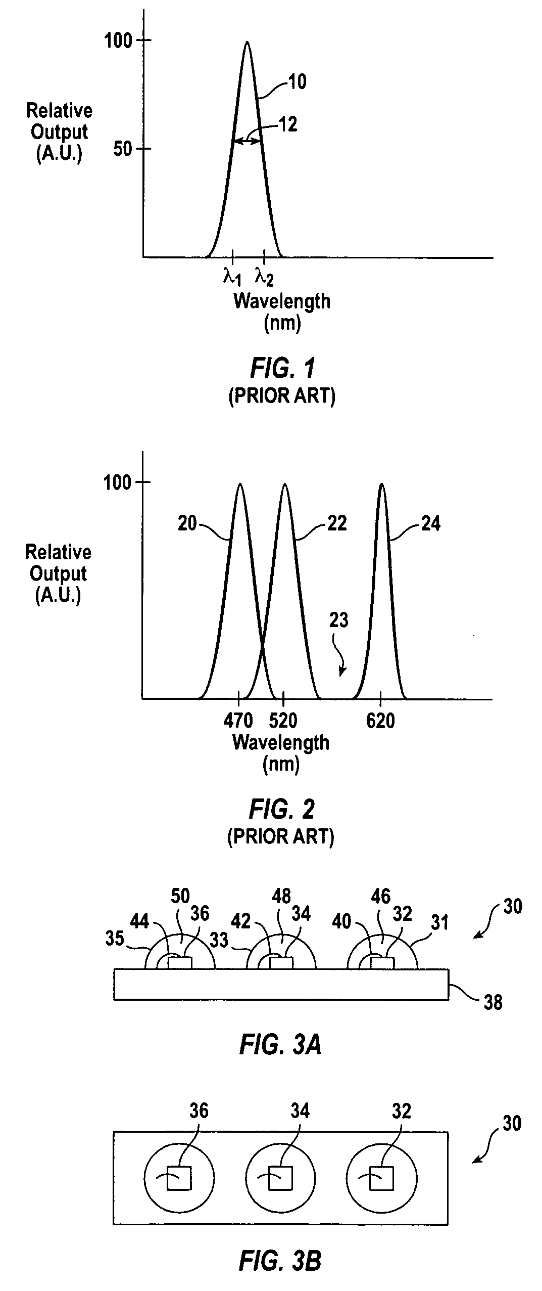
[0026] Prior art flash modules tend to be peaky and discontinuous. The dips between spectral peaks can result in poor color fidelity. In particular, a combined spectral emission such as the one shown in FIG. 2 is missing spectral emission in the greenish-yellow region. A combined spectral emission lacking in light in this region will not be able to faithfully reproduce a good color image of the subject. This problem is particularly bad if the spectral reflectivity of the subject lies primarily where the spectral emission of the flash module is weak or missing.

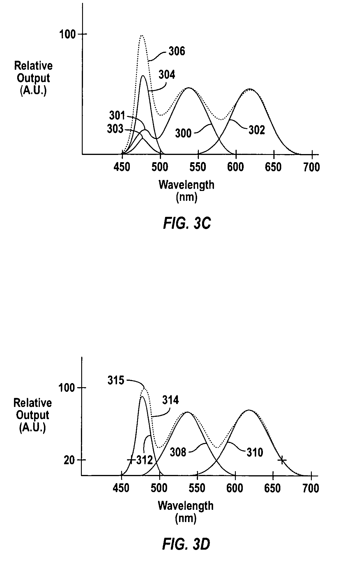
[0027] The spectral emission of a flash module can be improved by using LEDs that have large FWHMs, such as greater than 50 nm. In one embodiment, at least one of a red LED, a green LED, and a blue LED has an FWHM greater than 50 nm. In a further embodiment, at least two of a red LED, a green LED, and a blue LED have FWHMs greater than 50 nm. In a yet further embodiment, each of a red LED, a green LED, and a blu...


PUM


Abstract

A light-emitting diode (“LED”) device includes a plurality of LEDs. Each LED in the plurality of LEDs is adjacent to at least one other of the plurality of LEDs. At least one of the plurality of LEDs has a radiation with a full-width-half-maximum greater than 50 nm.

Description

CROSS-REFERENCE TO RELATED APPLICATIONS [0001] Not applicable. STATEMENT REGARDING FEDERALLY SPONSORED RESEARCH OR DEVELOPMENT [0002] Not applicable. REFERENCE TO MICROFICHE APPENDIX [0003] Not applicable. BACKGROUND OF THE INVENTION [0004] The invention relates to light-emitting diode (“LED”) devices, and more particularly to LED devices having a plurality of LEDs arranged in an array for use in flash applications. [0005] An LED is a semiconductor device capable of emitting light when an electric current flows through it. LEDs are used in many applications, such as electronic displays, traffic signals, and video signs. LEDs emit monochromatic light, i.e., the wavelength of light emitted by an LED falls within a narrow range, typically about 20-50 nanometers (“nm”). However, different types of LEDs emit different wavelengths (colors) of light. LEDs are often characterized by the full-wave-half-maximum (“FWHM”), which is the spread of wavelength emitted by an LED at 50% of maximum ra...

Claims


Application Information

Patent Timeline
Patent Type & Authority Applications(United States)
IPC IPC(8): F21V9/00F21K99/00
CPCF21K9/00G03B15/03H01L25/0753H01L2224/48091H04M1/22H04N5/2256H01L2924/00014H01L2924/12041Y10S362/80H01L33/504F21Y2113/13H04N23/56
Inventor NG, KEE YEANCHENG, HENG YOWKUAN, YEW CHEONG
Owner EPISTAR CORP
Why Eureka
Try Eureka