Air cooling configuration for gaming machine

a technology for gaming machines and cooling configurations, applied in mechanical equipment, instruments, sport equipment, etc., can solve problems such as undesirable normal configuration of gaming machines, excessive high-power gaming machines, and inability to meet the needs of customers, and achieve the effect of reducing the size of gaming units

Inactive Publication Date: 2006-06-15
COLE KEPRO INT
View PDF47 Cites 11 Cited by
  • Summary
  • Abstract
  • Description
  • Claims
  • Application Information

AI Technical Summary

Benefits of technology

[0029] The gaming unit of the invention has a number of advantages. Among other things, the configuration of the unit, including the housing and the individual components minimizes the size of the gaming unit. The small size of the unit allows the unit to be located in existing and new environments where little support surface area is available. The unit also has a small depth, allowing the unit to be placed where the area beneath the support surface is minimal, such as in a bar surface located above a cooler or refrigerator.

Problems solved by technology

In some instances, this normal configuration of a gaming machine is undesirable.
First, the height of the gaming machine is such that if it is placed on the bar surface, it is positioned too high to be used by a customer.
A first drawback is the method of mounting the unit to the bar surface.
Current bar top units also often still suffer from drawbacks relating to their application.
First, the depth of these bar top units is still quite great, and does not permit the units to be placed in a location of the bar where a cooler is located under the bar surface.
Another problem is that the units are not arranged to be readily serviceable.
First, some bar top gaming units are not configured for easy service by a technician in the event of a malfunction.
Components of the unit maybe layered upon one another within the housing, making it difficult for the technician to reach components positioned deep within the unit.
On the other hand, the depth of the unit is very large, preventing it from being used in many locations.
Also, the units are not configured for simple and secure service by a gaming operator, such as to empty a coin hopper or remove a full cash box.

Method used


Image

  • Air cooling configuration for gaming machine
  • Air cooling configuration for gaming machine
  • Air cooling configuration for gaming machine

Examples


Embodiment Construction

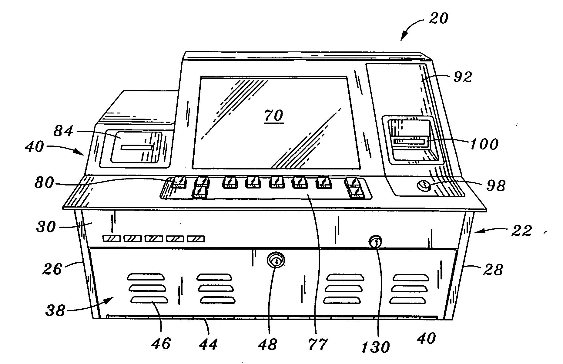
[0039] The invention is a bar top gaming unit. In the following description, numerous specific details are set forth in order to provide a more thorough description of the present invention. It will be apparent, however, to one skilled in the art, that the present invention may be practiced without these specific details. In other instances, well-known features have not been described in detail so as not to obscure the invention.

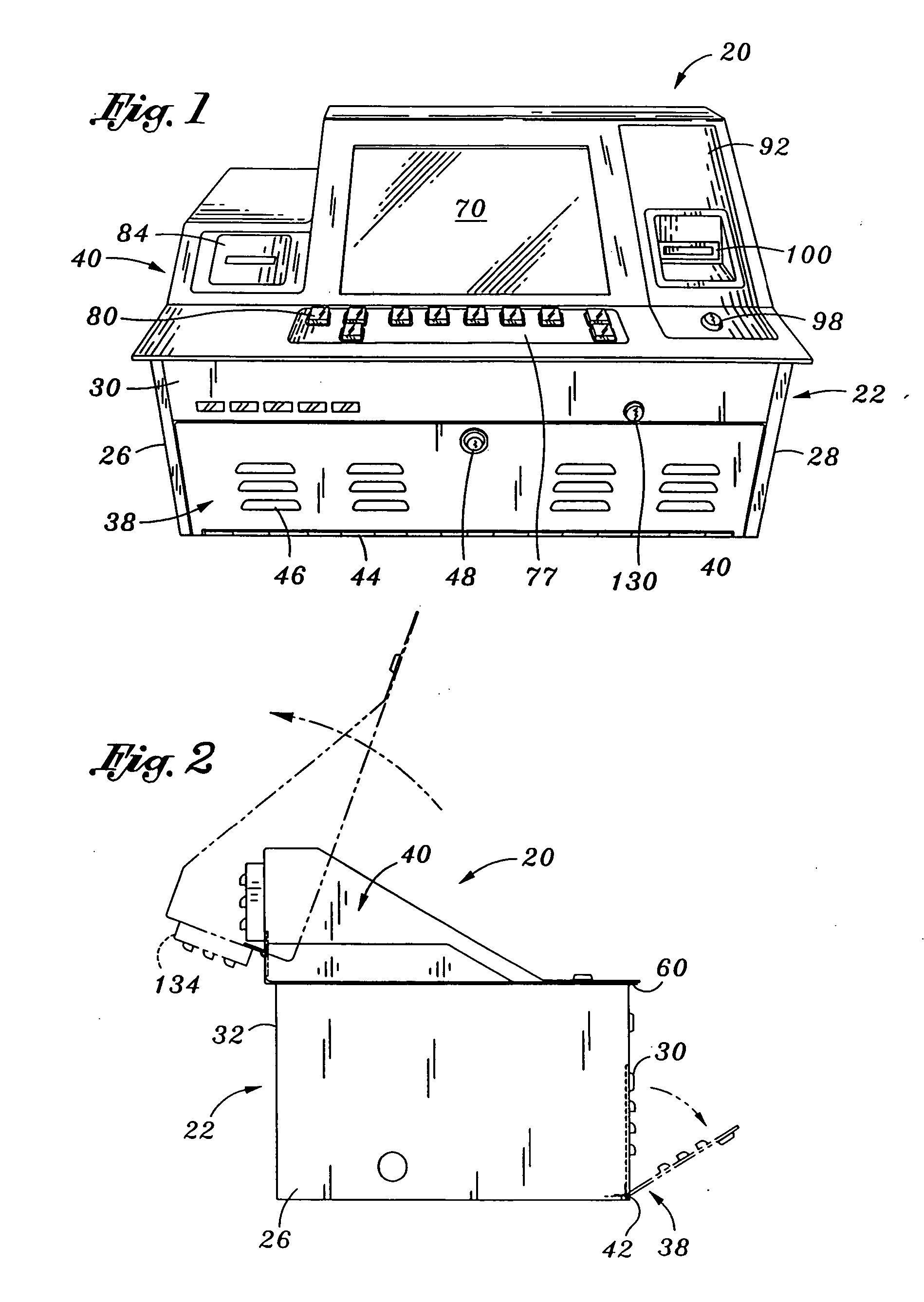
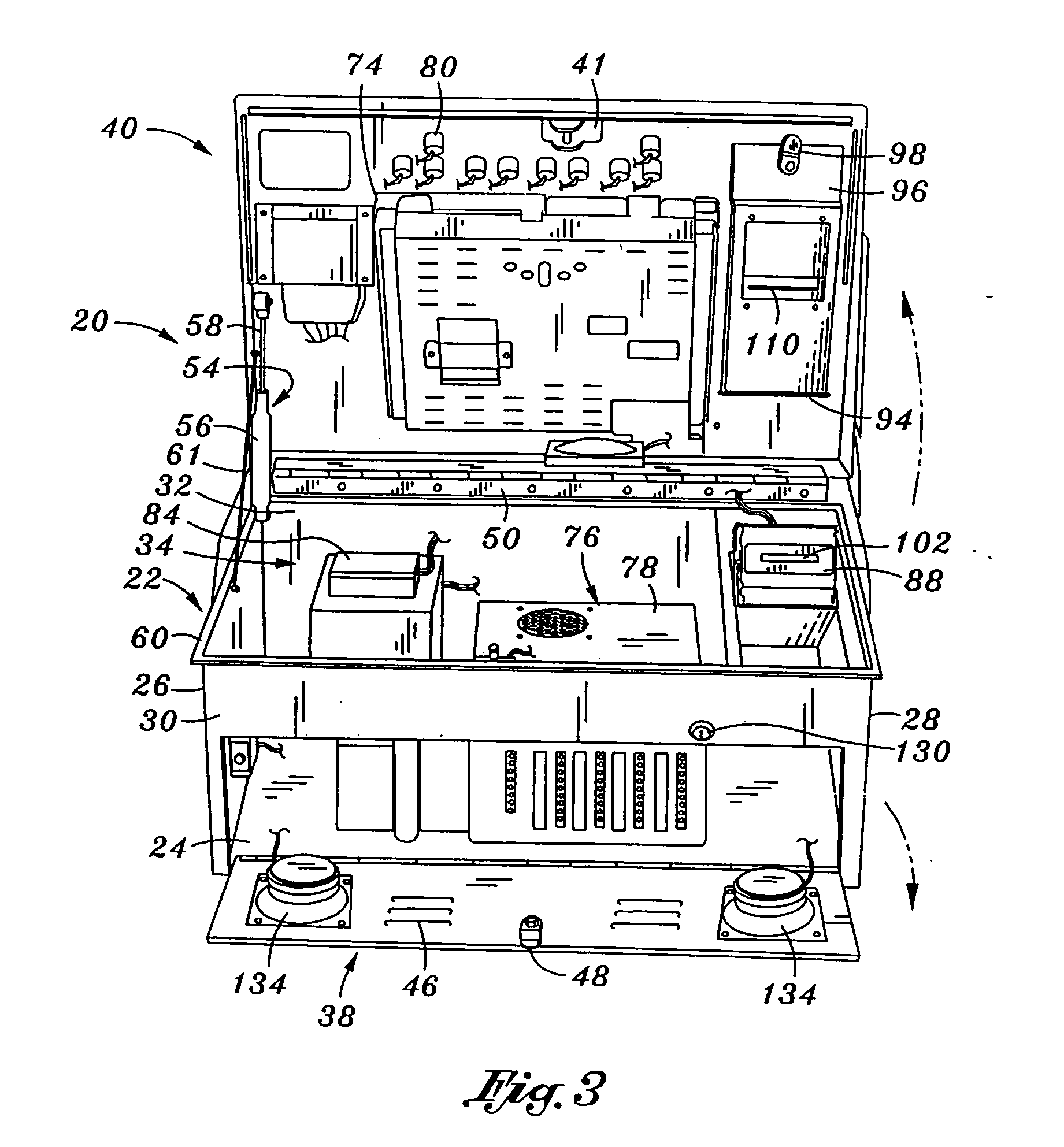
[0040] One embodiment of a bar top gaming unit 20 will be described with reference to FIGS. 1-4. Referring first to FIGS. 2 and 4, the bar top gaming unit 20 includes a housing 22. In one embodiment, the housing 22 is defined by a bottom or base 24 and at least one wall extending upwardly from the base. In a preferred embodiment, first and second sides 26,28 extend upwardly from opposing edges of the base 24. The housing 22 also includes front and rear walls 30,32 which extend upwardly from the base 24. The front and rearwalls 30,32 extend between the first...


PUM


Abstract

A gaming machine has a housing and a top panel which extends over an open top of the housing. A display is mounted to the top panel and a gaming controller is located within the housing beneath the display. Cooling air is drawn through one or more intakes in a front of the housing and expelled through one or more exhausts in a rear portion of the top panel at a location above the air intakes. The cooling air passes through a space between the gaming controller and the display, cooling those components.

Description

RELATED APPLICATION [0001] This application is a continuation of U.S. application Ser. No. 10 / 686,957, filed Oct. 15, 2003, now U.S. Pat. No. 6,976,919, which is a divisional of U.S. patent application Ser. No. 09 / 875,773, filed Jun. 5, 2001, now U.S. Pat. No. 6,688,984.FIELD OF THE INVENTION [0002] The present invention relates to gaming units configured to presenting games, and more particularly to an air cooling configuration for a gaming machine. BACKGROUND OF THE INVENTION [0003] A wide variety of devices exist which are configured to present one or more games. These devices include the well known slot machine and video poker machine, each of which is configured to present at least one gambling or wager-type event. By gambling event, it is meant a game which requires a player to place a bet, such as a monetary wager, for the opportunity of winning an award if the outcome of a presented game is a winning outcome. [0004] Slot and video machines have a wide variety of configuratio...

Claims


Application Information

Patent Timeline
Patent Type & Authority Applications(United States)
IPC IPC(8): A63F9/24G07F17/32
CPCG07F17/32G07F17/3216Y10T292/1047Y10T70/5031
Inventor COLE, JOSEPH W.
Owner COLE KEPRO INT
Why Eureka
Try Eureka