Magnetic dampening unit for an exercise gym apparatus

Inactive Publication Date: 2006-06-15
MA CHI HSIU +1
View PDF9 Cites 14 Cited by
  • Summary
  • Abstract
  • Description
  • Claims
  • Application Information

AI Technical Summary

Benefits of technology

[0008] The main objective of the present invention is to provide a magnetic dampening

Problems solved by technology

Therefore, the dampening force of

Method used


Image

  • Magnetic dampening unit for an exercise gym apparatus
  • Magnetic dampening unit for an exercise gym apparatus
  • Magnetic dampening unit for an exercise gym apparatus

Examples


Example

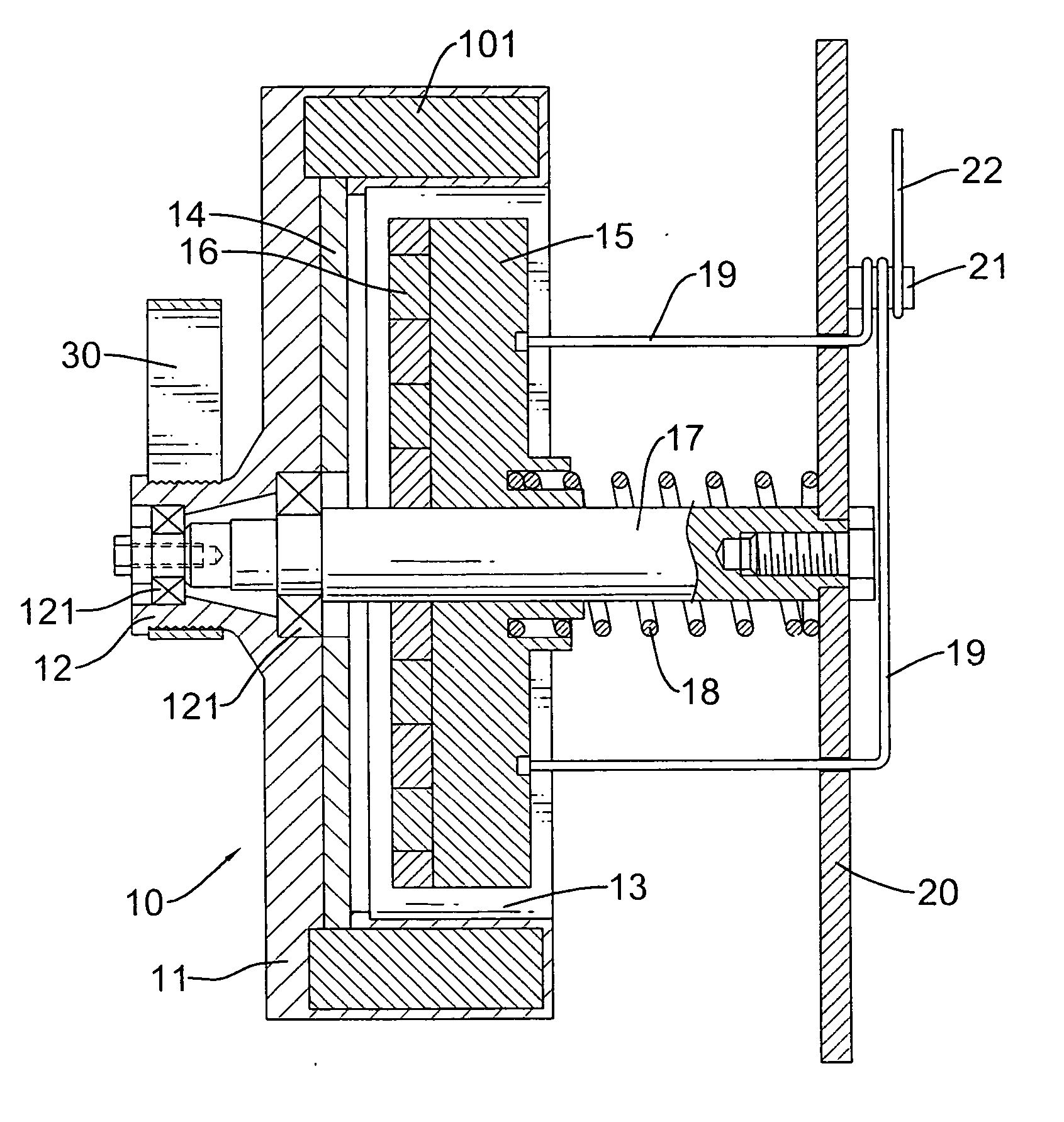
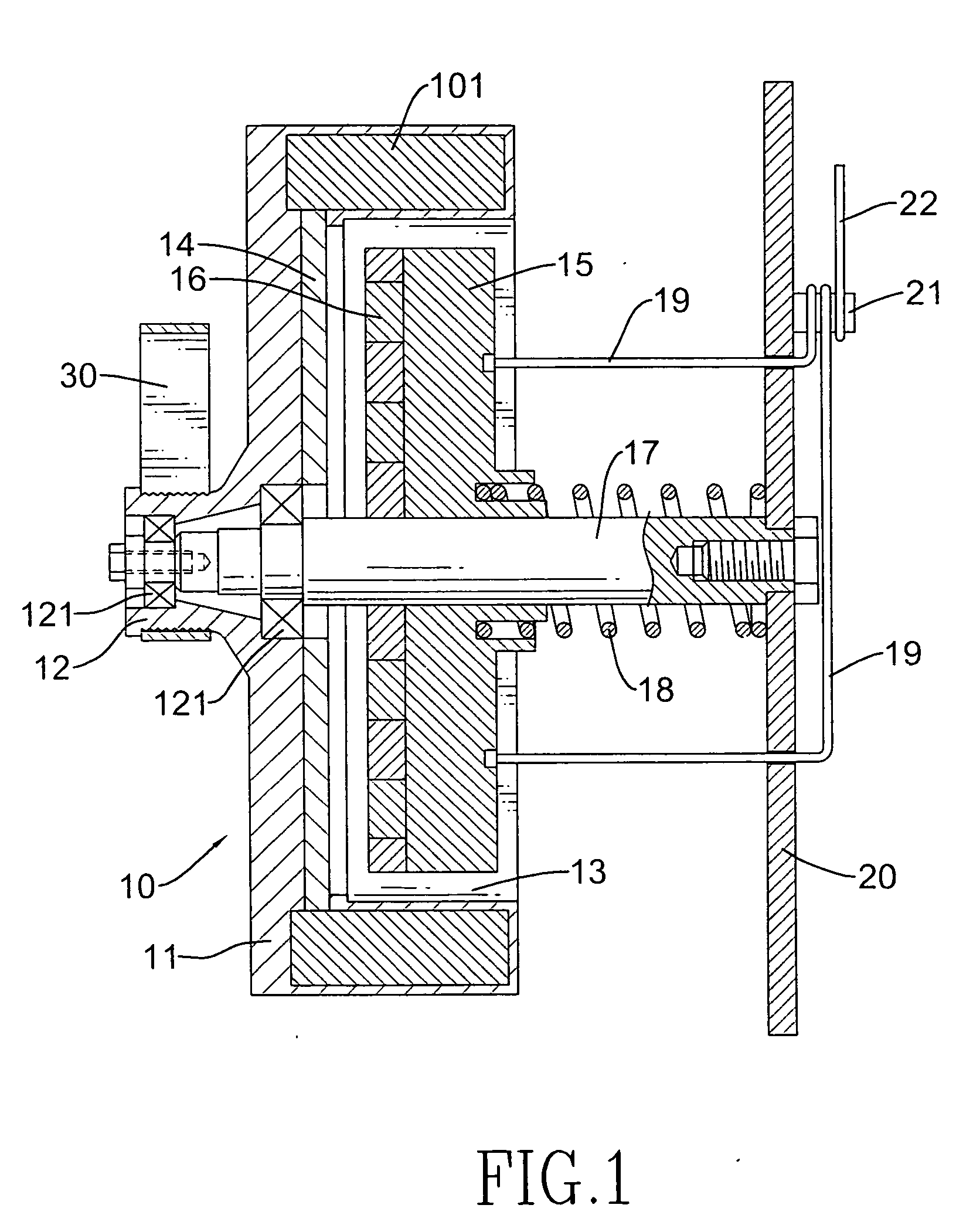
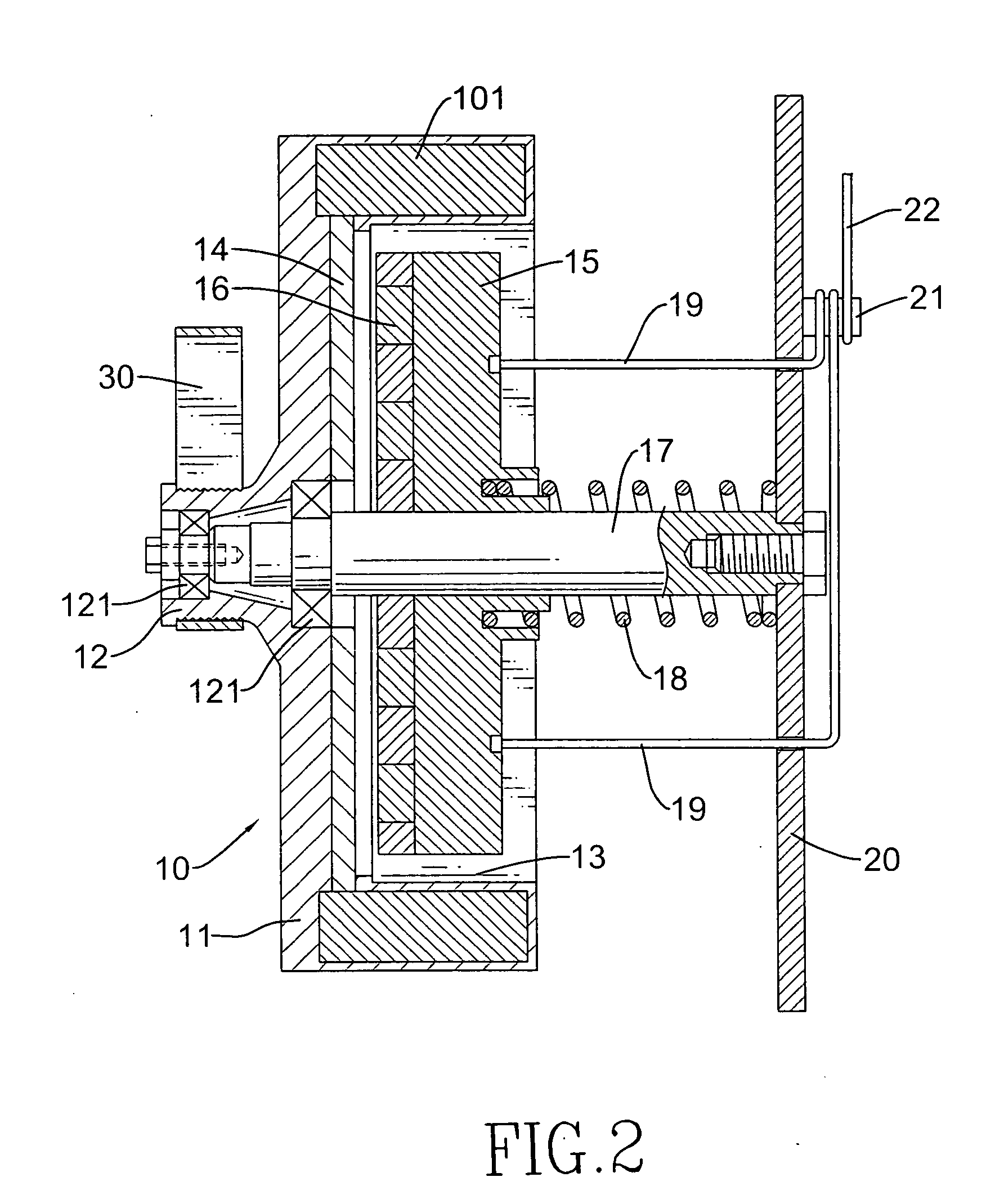
[0013] With reference to FIGS. 1 and 2, a magnetic dampening unit for an exercise gym apparatus in accordance with the present invention includes an axle (17) mounted on a plate (20) of the exercise gym apparatus (not shown). A flywheel (10) is rotatably mounted on the axle (17). The flywheel (10) is made of plastic material and provided with an iron ring (1101) embedded therein by means of injection molding. The flywheel (10) has a hub (11), and a stub (12) is formed at a central portion of the hub (11) and opposed to the plate (20). Multiple bearings (121) are received in the stub (12) to rotatably install the flywheel (10) on the axle (17). A recess (13) is defined in the flywheel (10) and faces the plate (20).

[0014] A disk (15) made of a non-magnetic metal is movably mounted on the axle (17) and received in the recess (13). A resilient member (18) is provided on the axle (17) between the disk (15) and the plate (20). Multiple permanent magnets (16) are mounted on an interior si...


PUM


Abstract

A magnetic dampening unit for an exercise gym apparatus includes a plate and an axle secured on the plate. A flywheel is rotatably mounted on the axle and has a hub. A stub is formed at a central portion of the hub and opposed to the plate. A non-magnetic metal member is provided in the flywheel and faces the plate. A disk is rotatably mounted on the axle and between the flywheel and the plate. A resilient member is mounted on the axle and between the disk and the plate. Multiple permanent magnets are provided on the disk with an alternate arrangement of N-polarities and S-polarities and facing the non-magnetic metal member. Two cables are provided on the disk and extend out from the plate. When drilling the flywheel for a dynamic balance, material waste will not be drawn to the magnets and the flywheel can be easily cleaned.

Description

BACKGROUND OF THE INVENTION [0001] 1. Field of the Invention [0002] The present invention relates to an exercise gym apparatus, and more particularly to a magnetic dampening unit for an exercise gym apparatus [0003] 2. Description of Related Art [0004] With reference to FIG. 3, in a conventional exercise gym apparatus, a magnetic dampening unit has an axle (48) mounted on a plate (50). A flywheel (40) is rotatably mounted on the axle (48), and a non-magnetic metal member (46) is mounted between flywheel (40) and the plate (50). A resilient member (49) is mounted on the axle (48) and between the non-magnetic metal member (46) and the plate (50). The flywheel (40) has a hub (41) and a stub (42) formed at a center of the hub (41). Bearings (421) are provided in the stub (42) to rotatably mount the flywheel (40) on the axle (48). A belt (60) is provided on the stub (42) and connected to a crank (not shown) of the exercise gym apparatus. [0005] A recess (43) is defined in the flywheel (4...

Claims


Application Information

Patent Timeline
IPC IPC(8): A63B22/06A63B69/16
CPCA63B21/0051A63B21/225
Inventor MA, CHI-HSIULU, SHU-CHIU
Owner MA CHI HSIU
Why Eureka
Try Eureka