
Light source device and projector

Inactive Publication Date: 2016-12-15
SEIKO EPSON CORP
View PDF2 Cites 1 Cited by
  • Summary
  • Abstract
  • Description
  • Claims
  • Application Information

AI Technical Summary

Benefits of technology

The patent describes a projector with two parts, a cartridge detection system and a light source detection system. These parts are made up of electrical resistive elements, which makes it simple to set up. The technical effect of this design is to improve the efficiency and accuracy of the projector.

Problems solved by technology

In a case where an installation posture of a projector is changed, a posture of a light source accommodated in the projector is also changed, and thus it is hard to cool the light source due to heat generated from the light source depending on an installation posture.
Therefore, there is a problem in that the service life of the light source is considerably reduced.

Method used


Image

  • Light source device and projector
  • Light source device and projector
  • Light source device and projector

Examples


embodiment

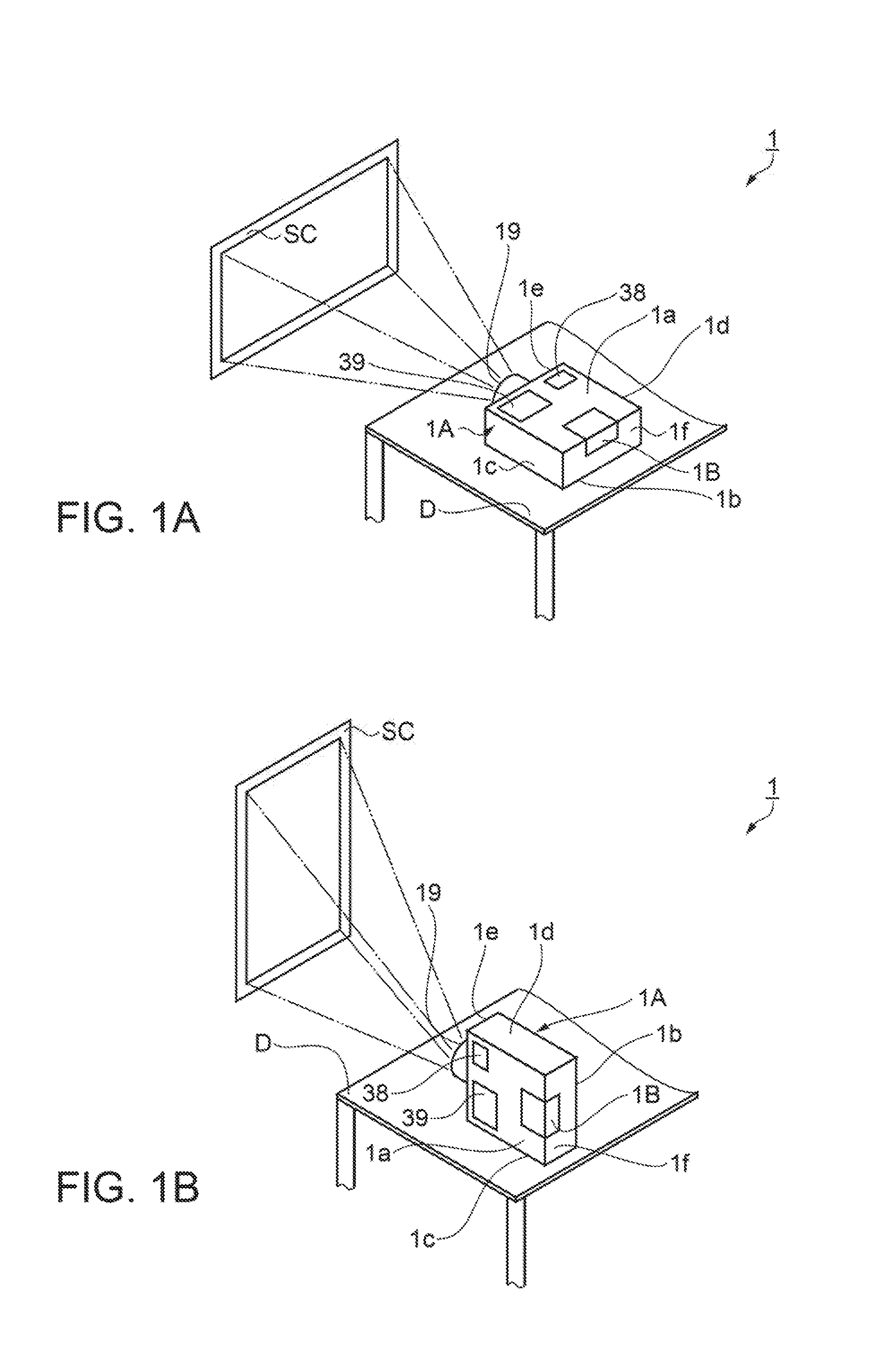
[0038]FIGS. 1A and 1B are schematic perspective views illustrating an installation posture of a projector 1 when projection is performed by using the projector 1 according to the present embodiment, in which FIG. 1A illustrates a normal installation posture, and FIG. 1B illustrates a side installation posture. With, reference to FIGS. 1A and 1B, a description will be made of an installation posture when projection is performed by using the projector 1.

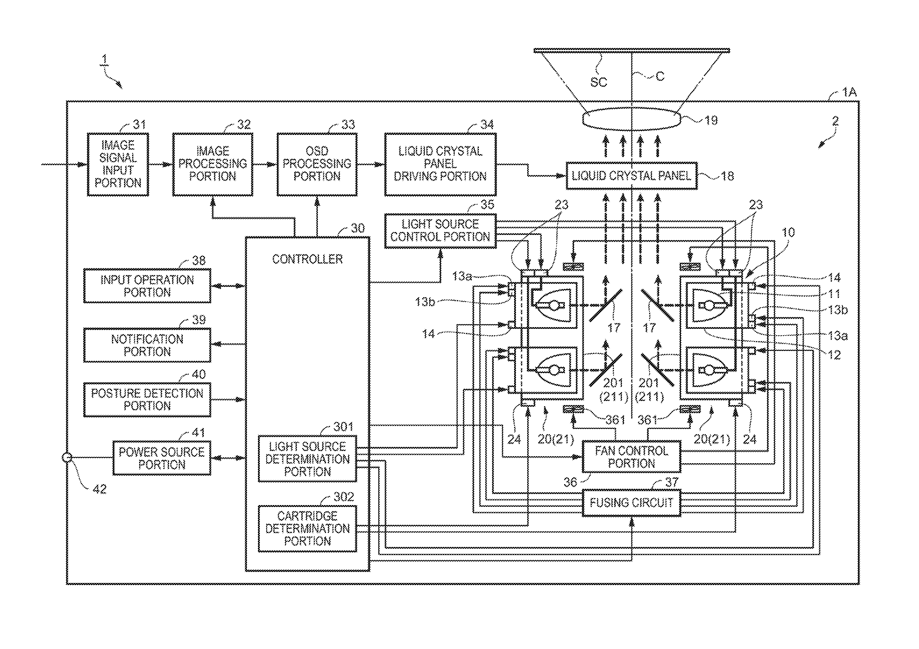
[0039]The projector 1 of the present embodiment modulates light emitted from a light source device 10 (light source 11) with a light modulation device according to image information, and enlarges and projects the modulated light on a screen SC or the like via a projection optical device 19. The projector 1 of the present embodiment is used to perform projection in two ways of installation postures including a normal installation posture illustrated in FIG. 1A and a side installation posture illustrated in FIG. 1B.

[0040]The projector 1 ...


PUM


Abstract

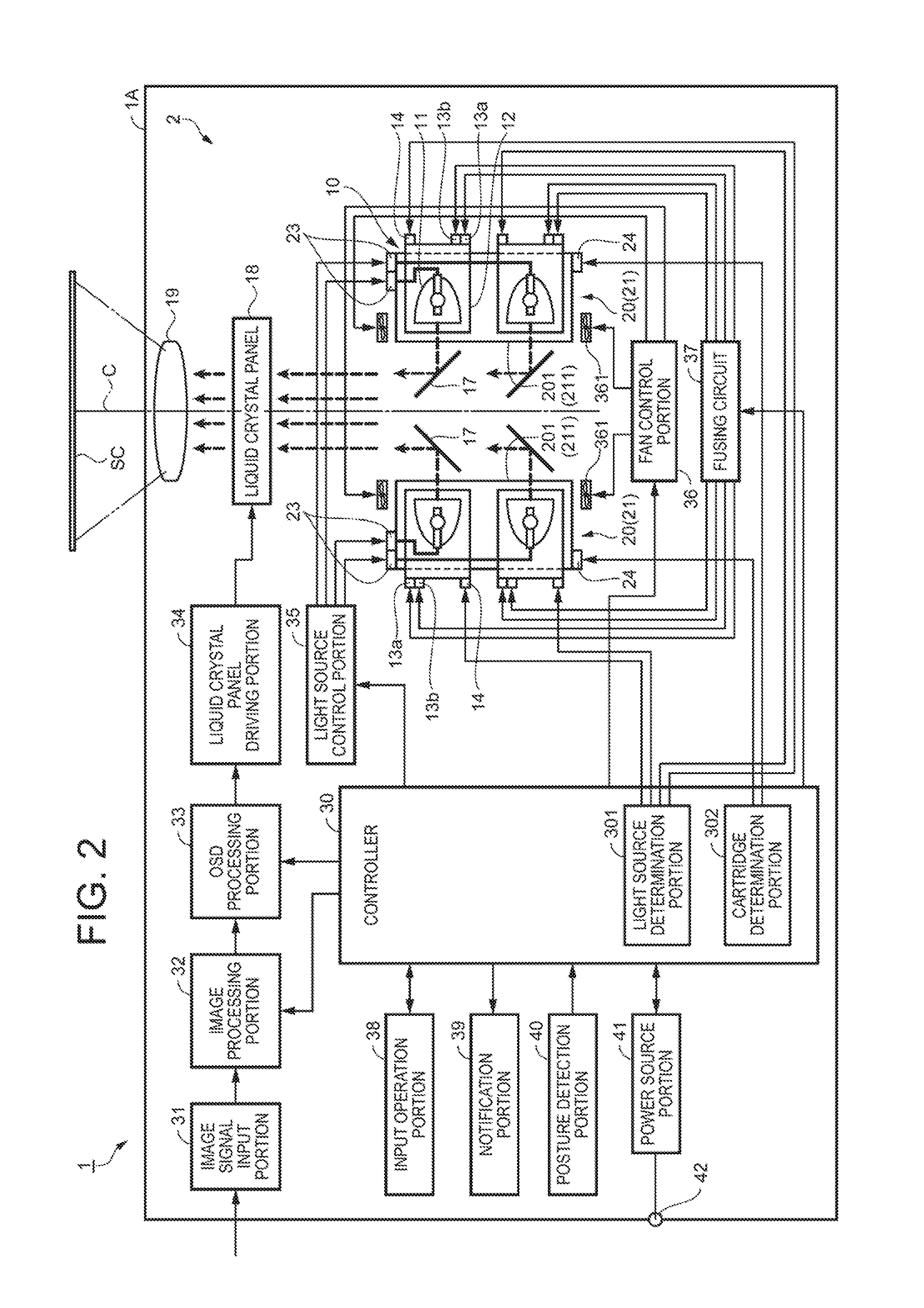
A light source device, which is incorporated into a projector and is used, includes a light source, and a light source case, in which the light source case includes fuses that are fused in a case where the light source device is in a predetermined use state, and a light source detection portion that detects whether or not the light source device is installed at a predetermined position in the projector. A projector includes a light source cartridge that is provided with a cartridge case accommodating two light source devices and corresponding to an installation posture of a projector main body, in which the cartridge case includes a cartridge detection portion that detects the corresponding installation posture.

Description

CROSS REFERENCE TO RELATED APPLICATION[0001]The entire disclosure of Japanese Patent Application No. 2015-118087, filed Jun. 11, 2015 is expressly incorporated by reference herein.BACKGROUND[0002]1. Technical Field[0003]The present invention relates to a light source device and a projector having the light source device.[0004]2. Related Art[0005]In related art, there is a projector in which light (emitted light) emitted from a light source is modulated by a light modulation device according to image information, and is enlarged and projected by a projection optical device. In recent years, the projector has been widely used for an event or the like, and achievement of high luminance of the projector has further progressed. There is a case of using a plurality of light sources in order to achieve high luminance of the projector.[0006]The number of agents lending out such a high luminance projector to organizers of events has increased.[0007]Regarding a posture (installation posture) ...

Claims


Application Information

Patent Timeline
IPC IPC(8): H04N9/31G03B21/20
CPCH04N9/3194H04N9/3164H04N9/3144G03B21/2086G03B21/2046G03B21/206G03B21/145G03B21/16
Inventor MIYATA, TAKAHIROSASAKI, FUMIHIDEHORIKO, YUKIHIROTAKIZAWA, TAKAHIRO
Owner SEIKO EPSON CORP
Learn More