Imaging optical system, lens unit, and image projection apparatus

Inactive Publication Date: 2013-02-07
CANON KK
View PDF7 Cites 0 Cited by
  • Summary
  • Abstract
  • Description
  • Claims
  • Application Information

AI Technical Summary

Benefits of technology

[0009]The present invention provides an imaging optical system that suppresses the deterioration of the imaging performance with an easy config

Problems solved by technology

However, when a light beam passes through a flat panel that is disposed so as to be inclined, various kinds of aberrations such as astigmatism are generated and therefore an imaging performance is deteriorated.
However, there is a skew ray that is a ray other than the inclination direction of the flat plate in real light beams, and therefore this configuration cannot correct aberration of the skew ray and the imaging performance cannot be sufficiently recovered.
Howeve

Method used


Image

  • Imaging optical system, lens unit, and image projection apparatus
  • Imaging optical system, lens unit, and image projection apparatus
  • Imaging optical system, lens unit, and image projection apparatus

Examples


Example

Embodiment 1

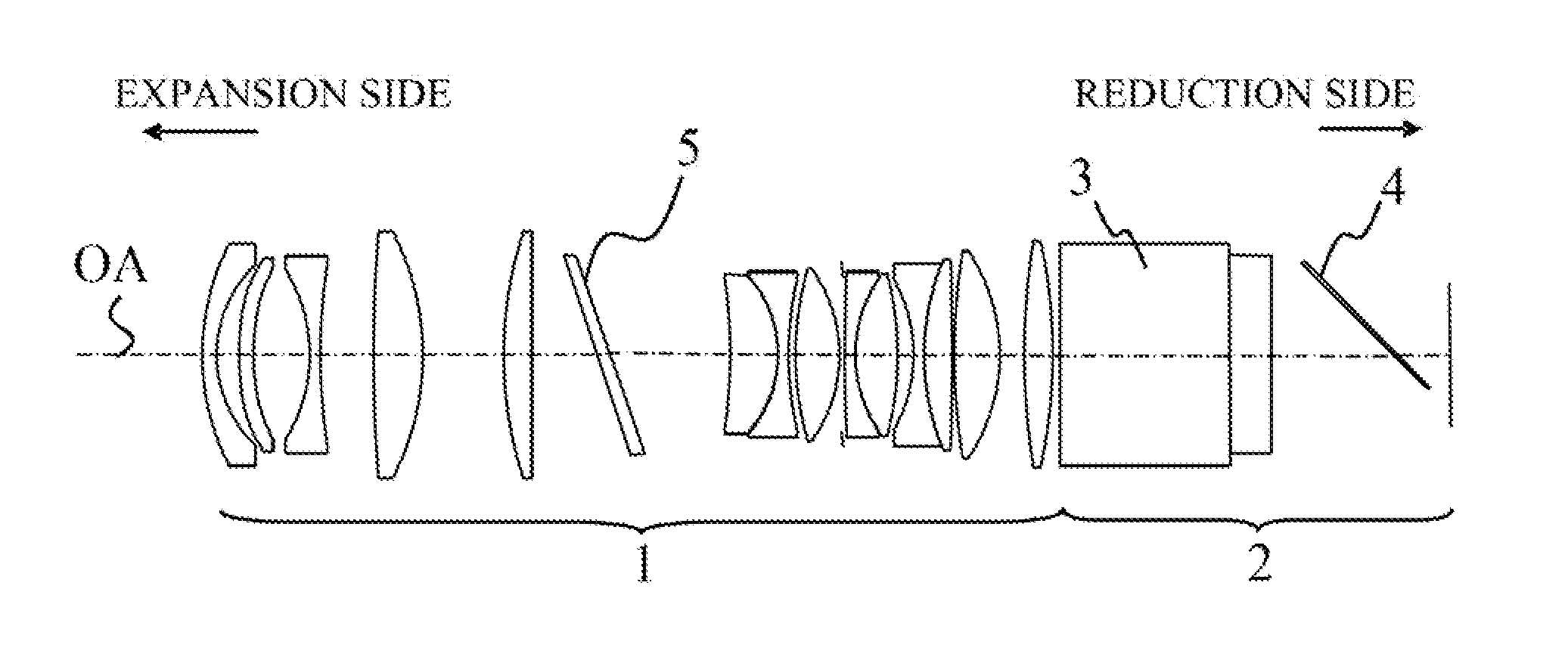
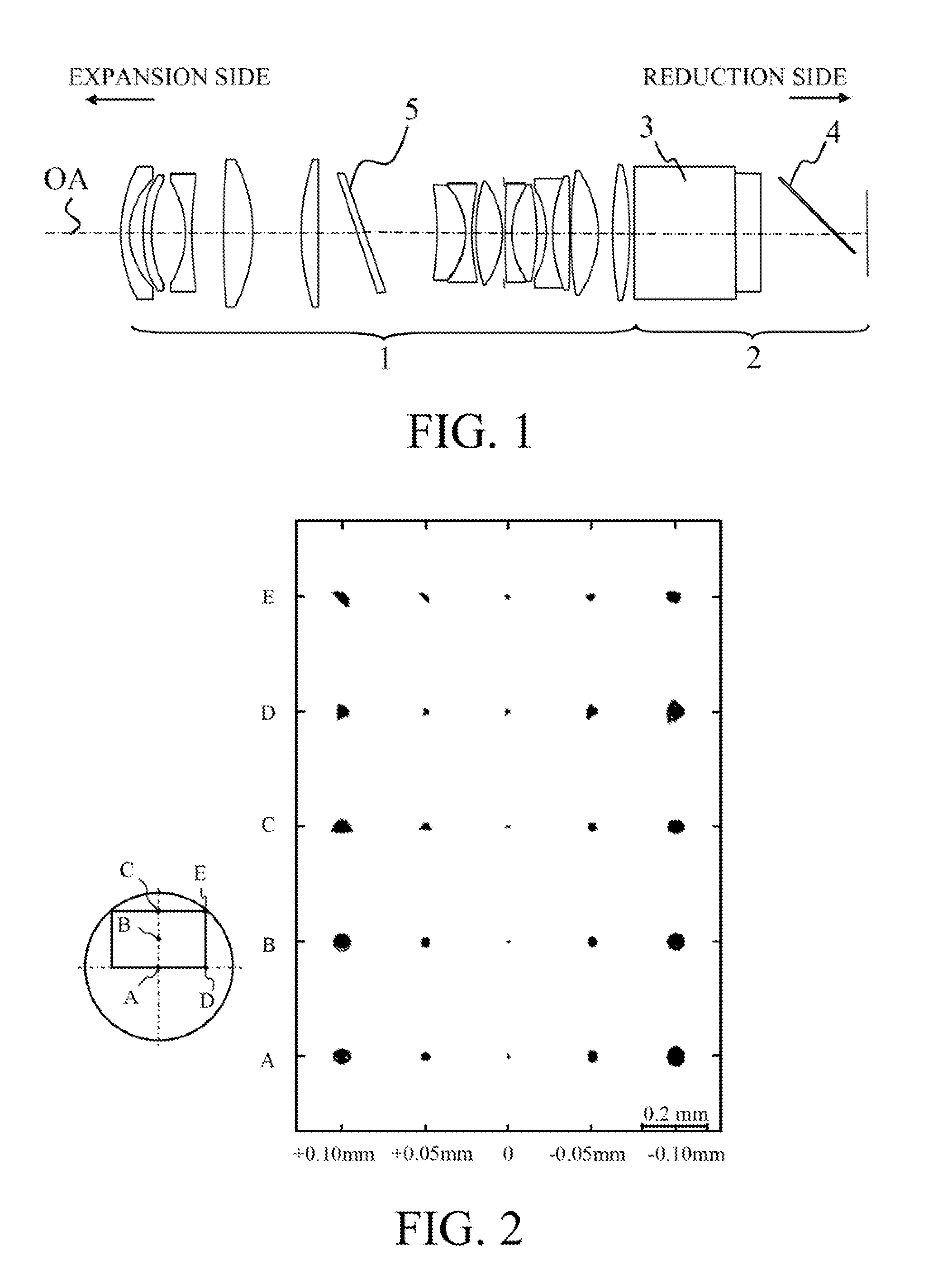
[0028]First of all, an imaging optical system in Embodiment 1 of the present invention will be described. FIG. 1 is a cross-sectional view of the imaging optical system in the present embodiment. The imaging optical system is configured by including a lens unit 1 and a color combining portion 2 (an optical path combining portion). The lens unit 1 is configured by including a plurality of optical elements (lenses). In the present embodiment, the lens unit 1 is a retro-focus type single focus lens which is configured by a total of 14 lenses, and a second lens is an aspherical lens (both sides). Moreover, the lens unit 1 includes a correction portion 5 that has a shape asymmetric to an optical axis OA inside it (in the optical path). The lens unit 1, for example, projects the light modulated by an image panel (a liquid crystal display element, or a light modulation element) onto a screen (a projection plane).

[0029]The color combining portion 2 is provided inside an area of ...

Example

Embodiment 2

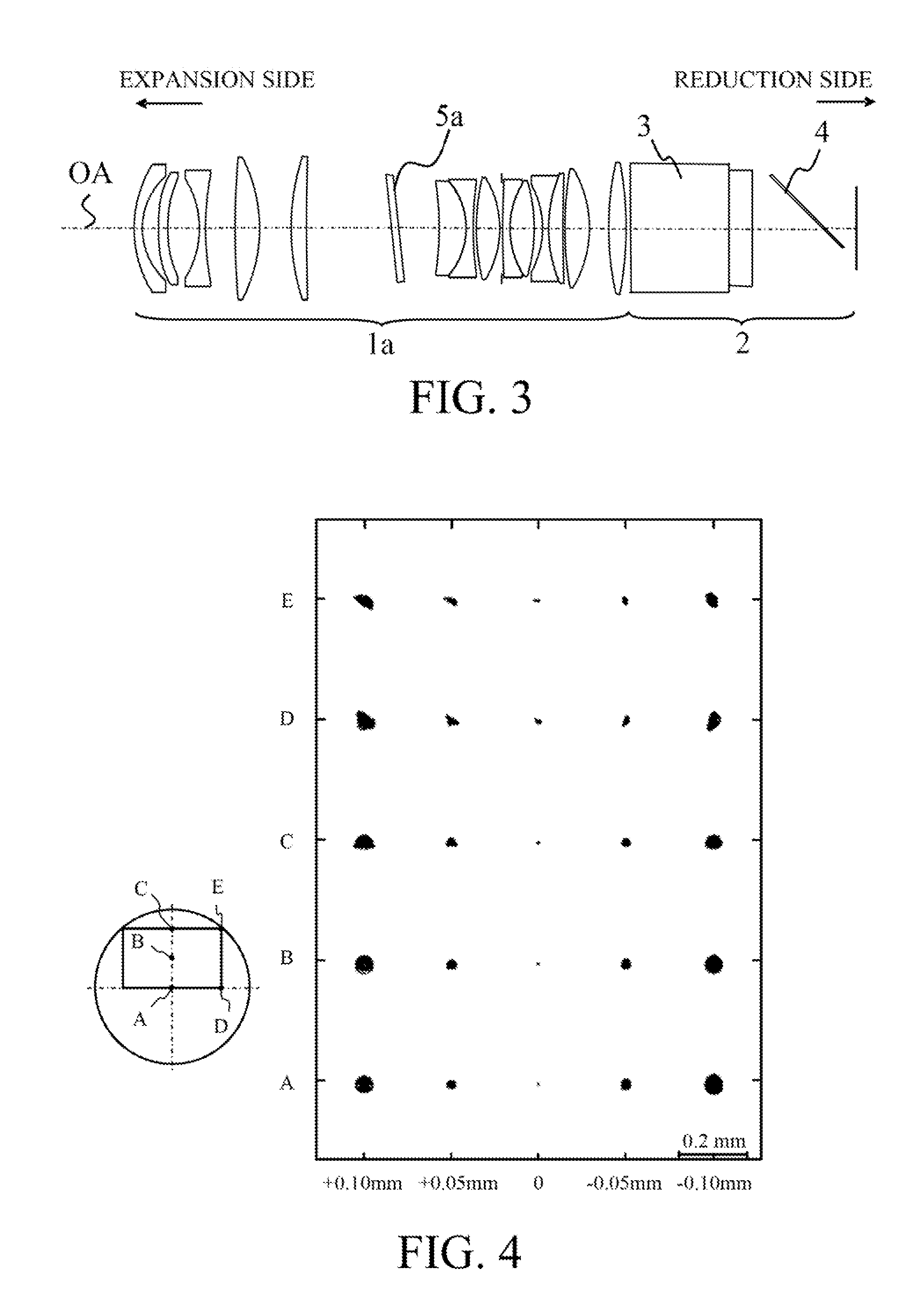
[0038]Next, an imaging optical system in Embodiment 2 of the present invention will be described. FIG. 3 is a cross-sectional view of the imaging optical system in the present embodiment. In the imaging optical system of the present embodiment, a correction portion 5a that is disposed inside a lens unit 1a has an apex angle of 0.59 degree and that is a cuneiform plate that is disposed so as to be inclined by around 6 degrees with respect to the optical axis OA. In addition, a surface at the reduction side of the correction portion 5a is a cylinder lens surface (a cylinder surface) that has a radius of curvature in a cross section in an inclination direction of the flat plate 4 (the cross section illustrated in FIG. 3). In the imaging optical system of the present embodiment, since the cylinder lens surface is provided in the imaging optical system of Embodiment 1, the correction of the skew ray and the correction of the image plane tilt can be more effectively realized, ...

Example

Embodiment 3

[0041]Next, an imaging optical system in Embodiment 3 of the present invention will be described. FIG. 5 is a cross-sectional view of the imaging optical system in the present embodiment. In the imaging optical system of the present embodiment, a correction portion 5b that is provided inside a lens unit 1b is provided as one lens surface instead of as a separated element, which is different from that of Embodiments 1 or 2.

[0042]The correction portion 5b of the present embodiment is achieved by designing the expansion side surface of the sixth lens to be a free-form surface. The free-form surface means a curved surface that is not rotationally symmetric to the optical axis OA. The free-form surface of the present embodiment is a curved surface where the thickness of a free-form lens at a coordinate position having the same distance from the optical axis OA is thin at the upper side with respect to the optical axis OA in FIG. 5 and is also thick at the lower side with resp...


PUM


Abstract

An imaging optical system includes a lens unit that includes a plurality of optical elements, and an optical path combining portion that includes a flat plate disposed so as to be inclined with respect to an optical axis of the lens unit, and the lens unit includes a correction portion that has a shape asymmetric with respect to the optical axis in a cross section that is parallel to both a normal of the flat plate and the optical axis.

Description

BACKGROUND OF THE INVENTION[0001]1. Field of the Invention[0002]The present invention relates to an imaging optical system, a lens unit, and an image projection apparatus.[0003]2. Description of the Related Art[0004]In a projector that uses a plurality of image panels, optical paths need to be combined before light beams enter a projection lens. When a reflective liquid crystal panel is used, a polarization splitting surface needs to be disposed between the reflective liquid crystal panel and the projection lens in order to separate incident light and emitted light. Conventionally, a projector that is configured by disposing a flat plate as a polarization splitting surface exists. However, when a light beam passes through a flat panel that is disposed so as to be inclined, various kinds of aberrations such as astigmatism are generated and therefore an imaging performance is deteriorated.[0005]Japanese Patent Laid-Open No. H06-337396 discloses a configuration in which two flat plates...

Claims


Application Information

Patent Timeline
IPC IPC(8): G03B21/14G02B9/00G02B27/10
CPCG02B27/005G02B15/14G02B13/16G02B15/145531
Inventor INOKO, KAZUHIRO
Owner CANON KK
Why Eureka
Try Eureka