Optical switch

Inactive Publication Date: 2007-11-01
JAPAN AVIATION ELECTRONICS IND LTD
View PDF0 Cites 0 Cited by
  • Summary
  • Abstract
  • Description
  • Claims
  • Application Information

AI Technical Summary

Benefits of technology

[0014]In view of the above problems, an object of the present invention is to provide an optical switch whic

Problems solved by technology

However, this optical switch is characterized in that the incident angles of light relative to the two mirrors are changed, and thus the two outgoing light beams reflected and emitted from the two mirrors do not have the same polarization state, that is, the configuration of this optical switch is not suitable for a request to match the polarization states of the outgoing light beams with high accuracy.
However,

Method used


Image

  • Optical switch
  • Optical switch
  • Optical switch

Examples


Example

[0030]An exemplary embodiment of the present invention will now be described based on examples with reference to the accompanying drawings.

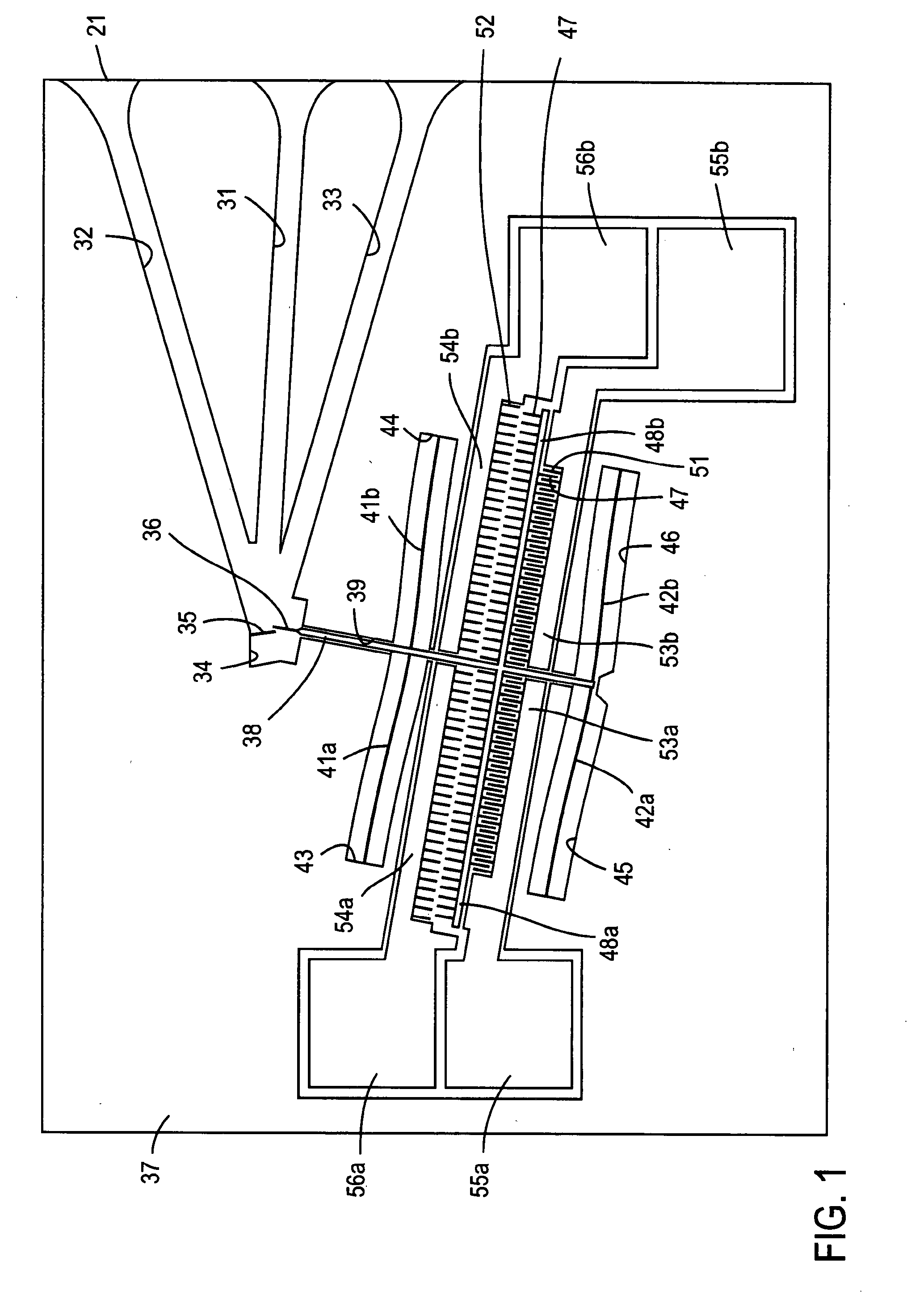
[0031]FIG. 1 shows the configuration of an example of a 1×2 optical switch according to the present invention. In this example, the optical switch is configured by a MEMS and is fabricated using an SOI (Silicon on insulator) wafer 20 having a three-layer structure of a silicon substrate 21, a silicon oxide film 22, and a silicon device layer 23 as shown in FIG. 4 (described later). The following constituent elements are formed by etching and removing the silicon device layer 23 and the silicon oxide film 22 on the silicon substrate 21 when necessary.

[0032]In this example, an optical fiber is used as optical waveguide means and three fiber grooves (fiber guides) 31 to 33 for positioning and receiving the ends of optical fibers are formed to extend from the inner side to the outer periphery of the silicon substrate 21. The inner ends of the fiber g...


PUM


Abstract

An optical switch, wherein the first and second output ports (optical fibers) are disposed on the opposite sides of the input port (optical fiber) so as to form acute angles with respect to the input port, the input port and the first output port are optically coupled to each other through a first mirror surface, and the input port and the second output port are optically coupled to each other through a second mirror surface. The incident angles of an incident light beam with respect to the mirror surfaces are equalized, and optical path lengths between the input port and the first and second output ports are equalized. The actuator inserts and withdraws the second mirror surface on a position at the front of the first mirror surface.

Description

TECHNICAL FIELD[0001]The present invention relates to an optical switch used in the field of optical communications and so on.BACKGROUND ART[0002]Of optical switches using mirrors for switching optical paths, some use one-time reflection on a mirror and others use reflection twice before light from an input port is coupled to an output port. For example, from the viewpoint of a change in the polarization state of light due to reflection, a smaller number of times of reflection on a mirror is more preferable and a smaller incident angle relative to the mirror is more preferable.[0003]FIG. 5A illustrates the configuration of patent literature 1 as a conventional example of a 1×2 optical switch. In FIG. 5A, reference numeral 11 denotes an input optical fiber and reference numerals 12 and 13 denote output optical fibers. Reference numeral 14 denotes a movable mirror and reference numeral 15 denotes a fixed mirror.[0004]In this example, light from the input optical fiber 11 is reflected ...

Claims


Application Information

Patent Timeline
IPC IPC(8): G02B26/08
CPCG02B6/3514G02B6/3518G02B6/3584G02B6/355G02B6/357G02B6/352
Inventor KATO, YOSHICHIKAHAMADA, YOSHIHIKOMORI, KEIICHIIMAKI, OSAMUKONDOU, KENJI
Owner JAPAN AVIATION ELECTRONICS IND LTD
Why Eureka
Try Eureka