Filling system for an anesthetic evaporator

Active Publication Date: 2006-06-22
DRAGERWERK AG
View PDF4 Cites 4 Cited by
  • Summary
  • Abstract
  • Description
  • Claims
  • Application Information

AI Technical Summary

Benefits of technology

[0007] The basic object of the present invention is to simplify a filling system of the type in terms of its construction such th

Problems solved by technology

The drawback of the prior-art filling system is that the anesthetic-specific coding on the adapter ne

Method used


Image

  • Filling system for an anesthetic evaporator
  • Filling system for an anesthetic evaporator
  • Filling system for an anesthetic evaporator

Examples


Example

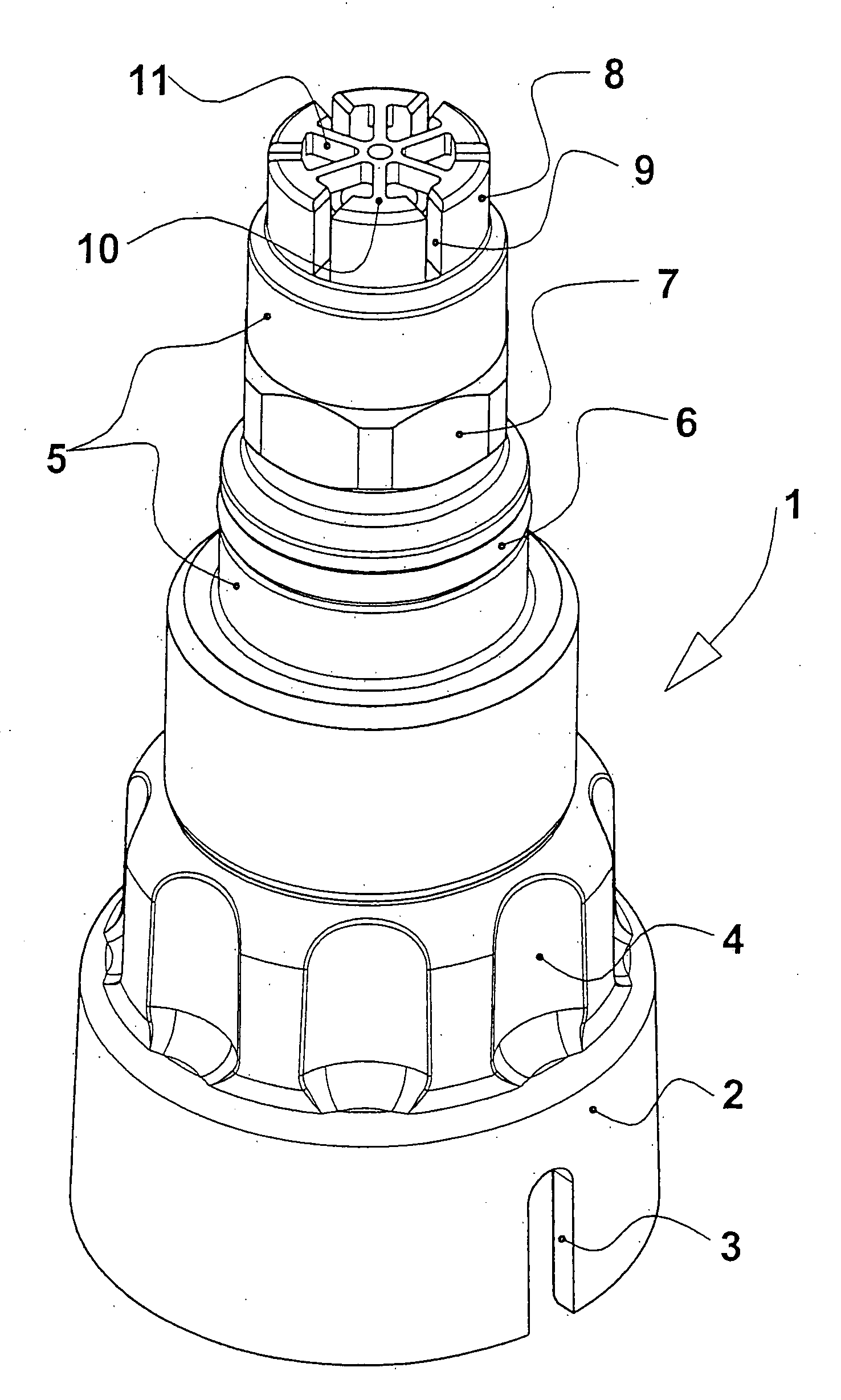
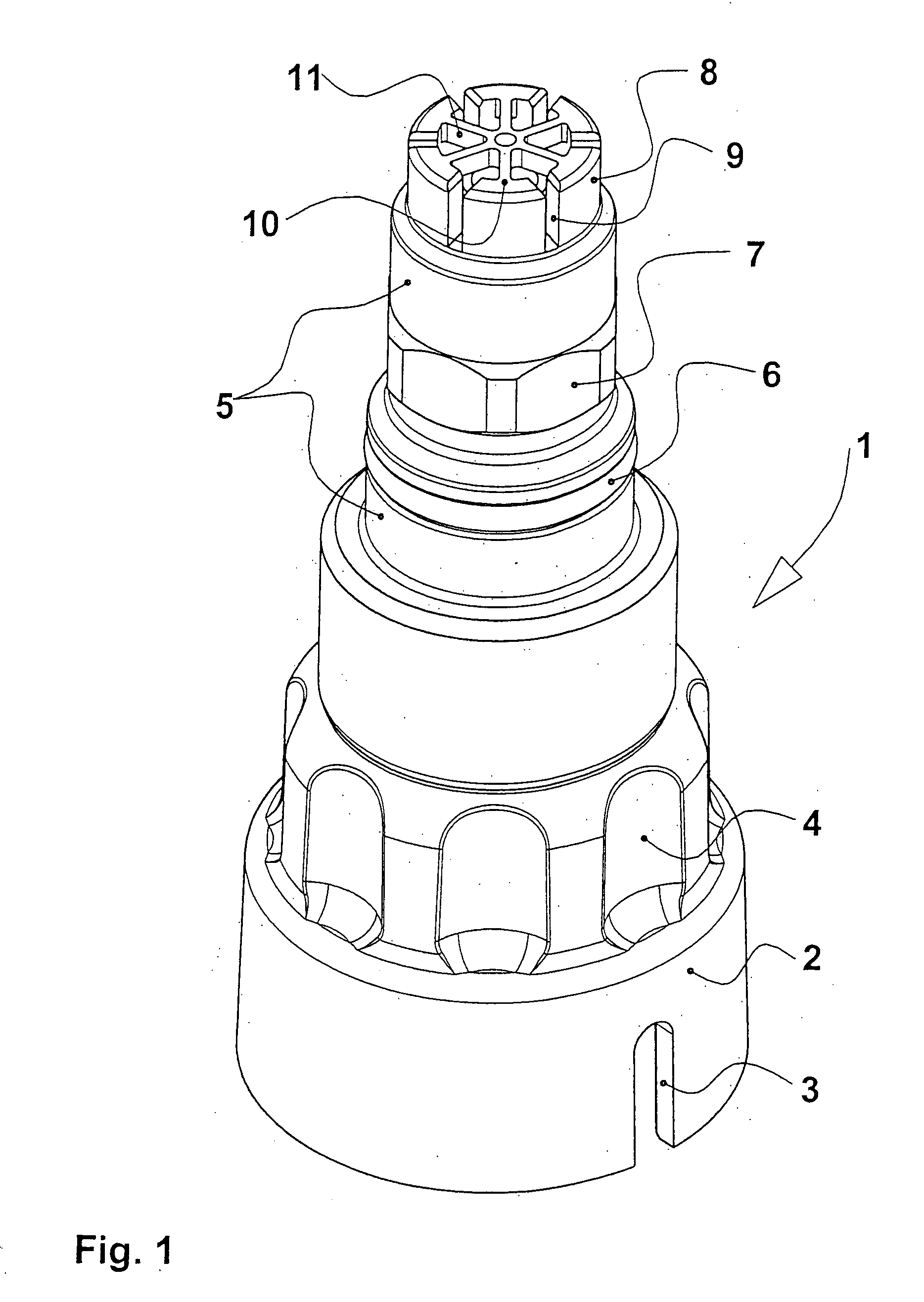
[0019] Referring to the drawings in particular, FIG. 1 shows a perspective view of a bottle adapter 1, which has a collet 2 on its underside for being screwed on a storage container for liquid anesthetic, not shown in FIG. 1. On its bottle collar, the storage container has an anesthetic-specific index collar, which is introduced into receiving grooves 3 of the collet 2. Thus, only a bottle adapter 1 that belongs to the anesthetic can be screwed onto the storage container. The screwing movement is facilitated by recessed grips 4 above the collet 2. An adapter neck 5 with an O-ring 6 and with an outer polygon 7 for the anesthetic-specific coding as well as an outlet neck 8 with radially extending slots 9 is located at the upper end of the bottle adapter 1. The top side 10 of the neck is designed as a star 11.

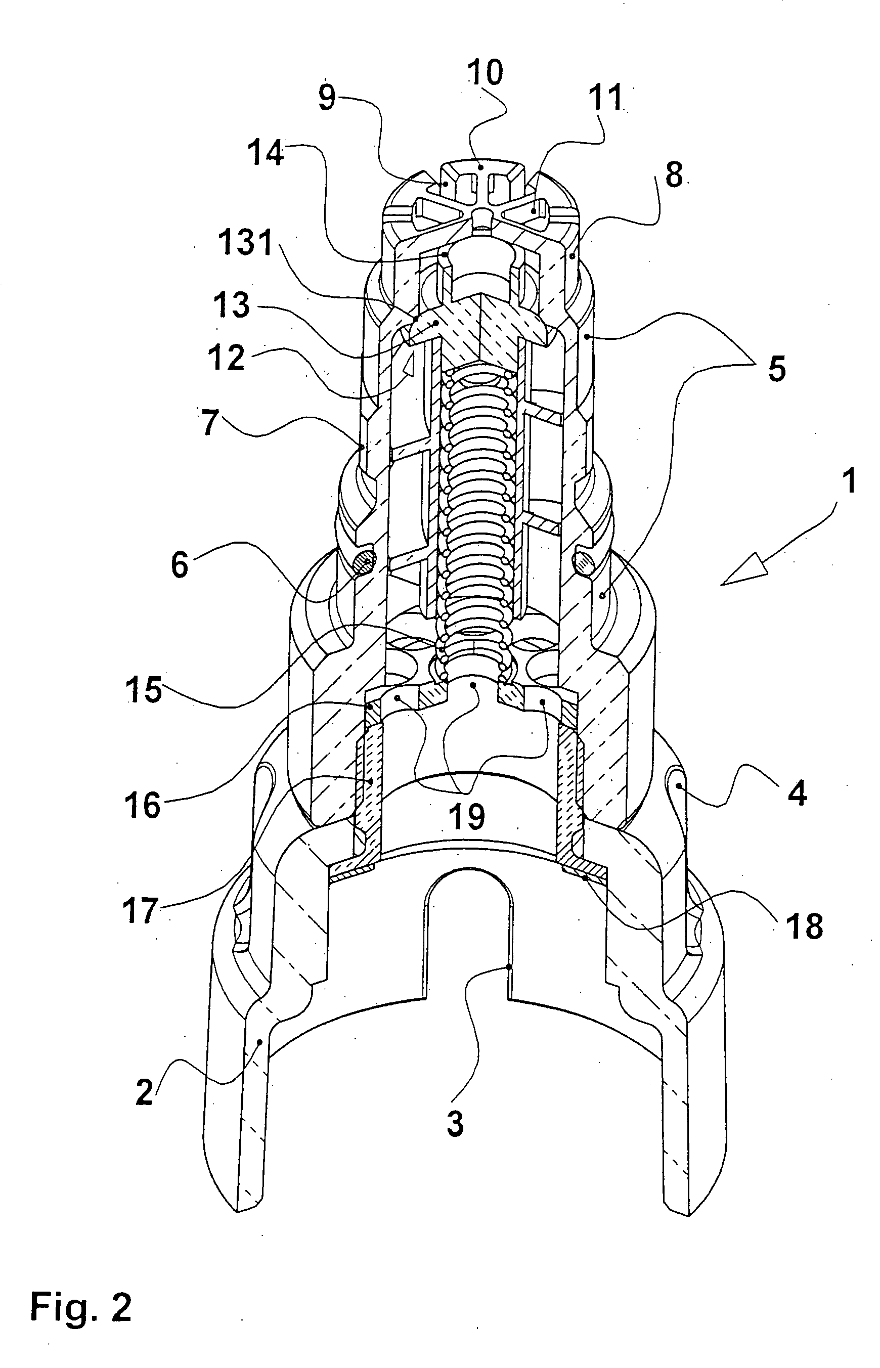
[0020]FIG. 2 illustrates the bottle adapter 1 according to FIG. 1 in a longitudinal section. Identical components are designated by the same reference numbers as in FIG. 1. A shu...


PUM

PropertyMeasurementUnit
Shapeaaaaaaaaaa

Abstract

A filling system for an anesthetic evaporator is improved such that an anesthetic-specifically coded adapter neck (5) of a bottle adapter (1) can be introduced into the filler neck of a filling device. An outer polygon (7) is provided on the bottle adapter and an inner polygon designed correspondingly thereto is provided on the filler neck as anesthetic-specific codings.

Description

CROSS REFERENCE TO RELATED APPLICATIONS [0001] This application claims the benefit of priority under 35 U.S.C. § 119 of German Patent Application 10 2004 061 392.3 Dec. 21, 2004 filed, the entire contents of which are incorporated herein by reference. FIELD OF THE INVENTION [0002] The present invention pertains to a filling system for an anesthetic evaporator. BACKGROUND OF THE INVENTION [0003] A filling system of the type has become known from U.S. Pat. No. 6,585,016 B1. To make it possible to fill liquid anesthetic into an anesthetic evaporator, a bottle adapter is necessary, which establishes the connection between the storage container for liquid anesthetic and the filling device at the anesthetic evaporator. A collet, which has two grooves for receiving an index collar arranged at the neck of the storage container, is provided at the bottle-side end of the bottle adapter. The index collar has an anesthetic-specific design, so that only the bottle adapter fitting the storage con...

Claims


Application Information

Patent Timeline
IPC IPC(8): B65B1/04B67D7/32
CPCA61M16/183A61M2205/6045
Inventor TURKER, AHMETREICHERT, DIRK-STEFANBUNKE, CLAUS
Owner DRAGERWERK AG
Why Eureka
Try Eureka