Electromagnetic surveying for hydrocarbon reservoirs

a hydrocarbon reservoir and electromagnetic technology, applied in the field of electromagnetic field, can solve the problems of inability to rely on these components alone for detecting hydrocarbon layers, inability to provide reliable statoil methods, and inability to widely think of electromagnetic surveying, etc., to achieve simple inversion modelling and improve the vertical resolution of structures

Active Publication Date: 2006-06-22
PGS GEOPHYSICAL AS
View PDF3 Cites 59 Cited by
  • Summary
  • Abstract
  • Description
  • Claims
  • Application Information

AI Technical Summary

Benefits of technology

[0021] The source electromagnetic signal can be emitted at different frequencies to obtain survey data at a plurality of different frequencies. Moreover, the source electromagnetic signal can be emitted at a variety of frequencies, preferably between 0.01 Hz and 10 Hz. The method can be advantageously repeated over the same survey area using different frequencies of source electromagnetic signal. Lower frequencies are generally preferred. By probing the subterranean strata at a number of different frequencies of source electromagnetic signal, it is possible to obtain improved vertical resolution of structures within the subterranean strata configuration.
[0022] The source signal can be from a horizontal electric dipole. Such a signal can be provided using existing equipment, and also allows relatively simple inversion modelling.

Problems solved by technology

However, EM surveying was not widely thought of as a technique that could be applied to finding hydrocarbon reservoirs.
However, it was established that the Statoil method could not provide reliable results, since the in-line data collected is incapable of distinguishing between a thin buried hydrocarbon layer of high resistivity situated in less resistive strata, on the one hand, and a non-hydrocarbon bearing rock formation in which the strata exhibits increasing resistivity with depth, on the other hand, the latter being a common feature of many large scale sedimentary structures.
While it is the vertical components of induced current flow which are most sensitive to the presence of a thin resistive layer, sole reliance on these components for detecting a hydrocarbon layer is not possible without ambiguity.
However, it has some limitations.
Firstly, since the two modes cannot be easily separated there will generally be a level of cross-talk between them at a detector and this can lead to ambiguities in the results.
This requires the surface vessel to make multiple passes over broadcast locations and can lead to long and complex tow path patterns.
Thirdly, the survey can only provide the best data possible at discrete source locations.
At other orientations, separation of the inductively and galvanically coupled signals becomes more difficult, and resulting data are less reliable.
Furthermore, in addition to the survey being time-inefficient, it is necessary to accurately follow a complex tow path which has to complement the detector layout, and the detectors themselves must also be carefully accurately arranged.
The difficulties in controlling both the position and the orientation of a towed source antenna, coupled with this need to accurately follow a particular tow path relative to the detector grid, is one of the major sources of error in surveys of these kind.
The disadvantages associated with the survey constraints imposed by the Sinha method are the price to pay for resolving the ambiguities inherent in the Statoil method.

Method used


Image

  • Electromagnetic surveying for hydrocarbon reservoirs
  • Electromagnetic surveying for hydrocarbon reservoirs
  • Electromagnetic surveying for hydrocarbon reservoirs

Examples


Embodiment Construction

[0055] A method of electromagnetic surveying for oil and other hydrocarbon reserves is described which does not require separate data acquisition of the response of a subterranean strata configuration to inductively and galvanically coupled modes. The new method can be performed using pre-existing survey equipment.

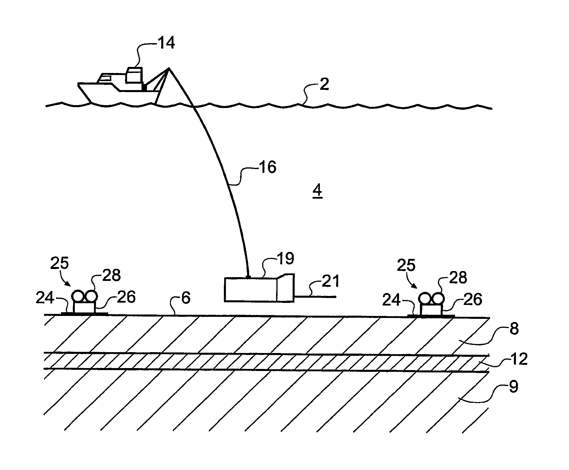
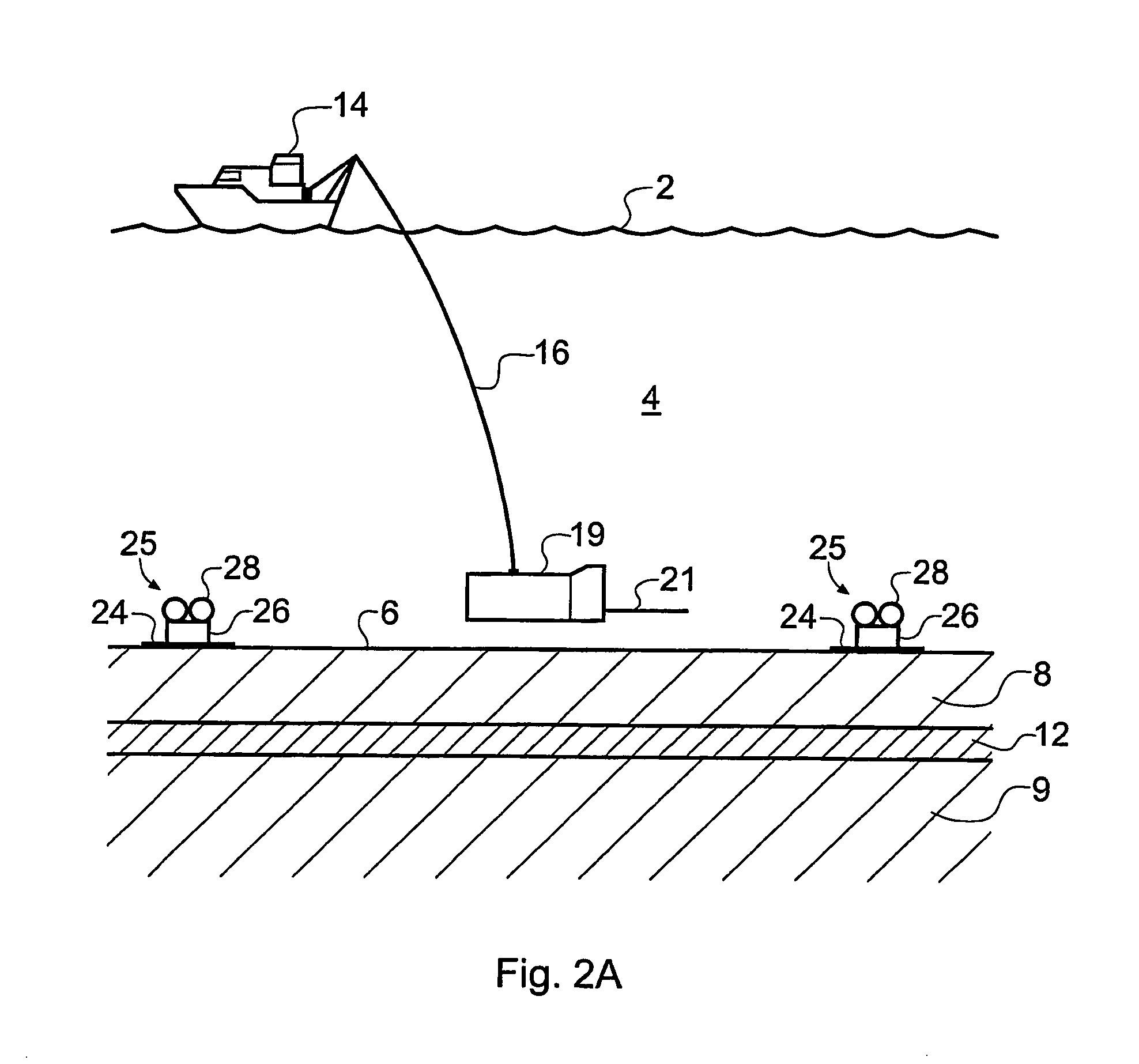
[0056]FIG. 2A schematically shows a surface vessel 14 undertaking EM surveying of a subterranean strata configuration in a way that is suitable for collecting survey data for carrying out the invention. The subterranean strata configuration includes an overburden layer 8, an underburden layer 9 and a hydrocarbon layer (or reservoir) 12. The surface vessel 14 floats on the surface 2 of the seawater 4. A deep-towed submersible vehicle 19 carrying a HED antenna 21 is attached to the surface vessel 14 by an umbilical cable 16 providing an electrical, optical and mechanical connection between the deep-towed submersible vehicle 19 and the surface vessel 14. The HED antenna broa...


PUM


Abstract

An electromagnetic survey method for surveying an area that potentially contains a subterranean hydrocarbon reservoir. The method comprises detecting a detector signal in response to a source electromagnetic signal, resolving the detector signal along at least two orthogonal directions, and comparing phase measurements of the detector signal resolved along these directions to look for a phase separation anomaly indicative of the presence of a buried hydrocarbon layer. The invention also relates to planning a survey using this method, and to analysis of survey data taken using this survey method. The first and second data sets may be obtained concurrently with a single horizontal electric dipole source antenna. The method is also largely independent of a source-detector pair's relative orientation and so provides for good spatial coverage and easy-to-perform surveying.

Description

BACKGROUND OF THE INVENTION [0001] The invention relates to seafloor electromagnetic (EM) surveying for oil and other hydrocarbon reserves. [0002] Geophysical methods for mapping subterranean resistivity variations by various forms of EM surveying have been in use for many years [1, 2, 3, 10]. In these methods, electric field detectors are placed on the seafloor at carefully chosen positions at ranges up to about 10 km from an electromagnetic source. Detector signals measured at the detectors are sensitive to variations in subterranean strata configuration resistivity beneath the area being surveyed. However, EM surveying was not widely thought of as a technique that could be applied to finding hydrocarbon reservoirs. [0003] More recently, it was proposed to use EM surveying to find hydrocarbon reservoirs. An early proposal by Statoil was to use the vertical current flow components to detect hydrocarbon layers [4, 5], since it is these components that are sensitive to the presence o...

Claims


Application Information

Patent Timeline
Patent Type & Authority Applications(United States)
IPC IPC(8): G01V3/10G01V3/12
CPCG01V3/083G01V3/12
Inventor MACGREGOR, LUCY M.SINHA, MARTINCWEAVER, RICHARD
Owner PGS GEOPHYSICAL AS
Why Eureka
Try Eureka