Formation resistivity combined inversion method based on while-drilling electromagnetic wave resistivity logging
A technology of resistivity logging and formation resistivity, which is applied in earthwork drilling, wellbore/well components, electrical digital data processing, etc. It can solve the problem of poor vertical resolution, shallow radial depth, and inability to respond well to resistivity Information and other issues, achieve good vertical resolution and reduce the workload of inversion
- Summary
- Abstract
- Description
- Claims
- Application Information
AI Technical Summary
Problems solved by technology
Method used
Image
Examples
Embodiment 1
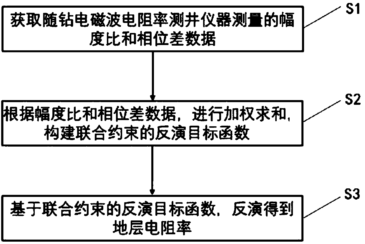
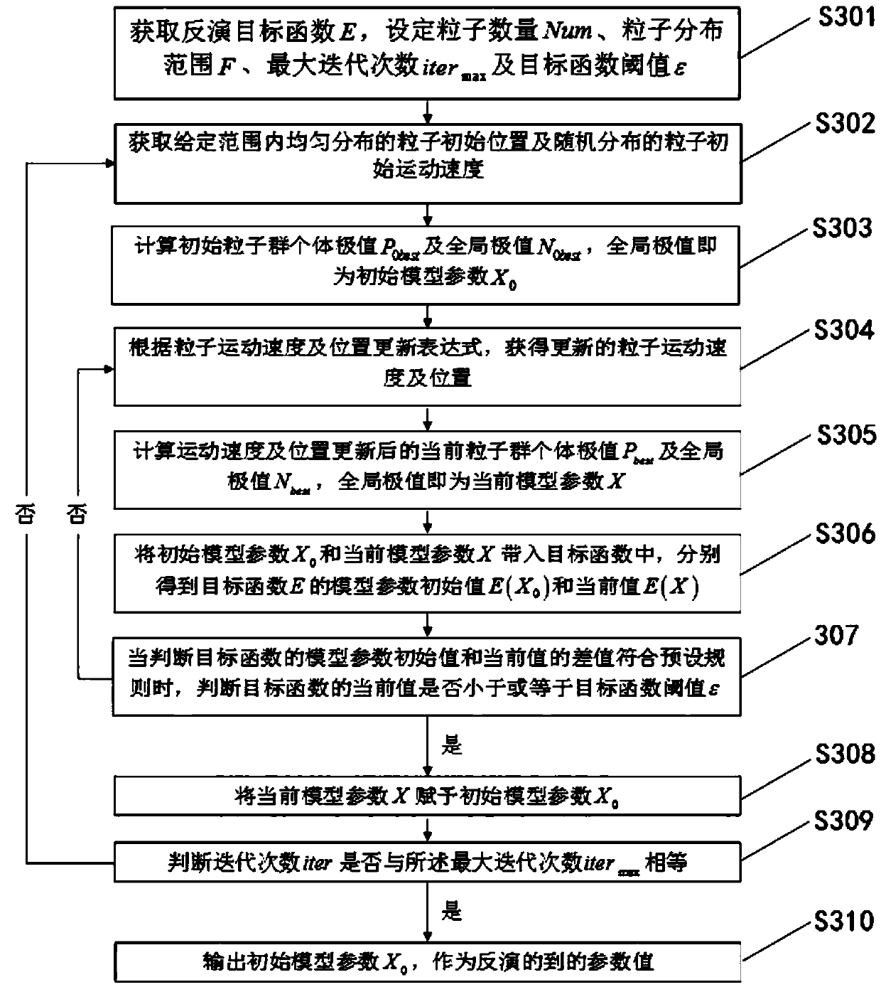
[0055] Model 1 is the invasion formation model, which divides the formation into invasion zones and undisturbed formations from the tool axis along the radial direction. In order to calculate the LWD tool response under different invasion conditions, the model invasion zone resistivity R in and undisturbed formation resistivity R t They are 2.5Ω.m and 10Ω.m respectively, and the calculation range of invasion depth is 0.1 to 6m. In order to invert to obtain the resistivity value of the intruded formation model, such as Figure 1~2 Shown: The specific formation resistivity inversion steps are as follows:
[0056] S1) The response value of the LWD electromagnetic wave resistivity logging tool in the above-mentioned intrusive formation model is used as the actual measurement data, and the response value of the tool in the uniform formation model is used as the forward modeling data.
[0057] S2) carry out weighted summation according to amplitude ratio and phase difference data,...
Embodiment 2
[0081] Example 2: Longitudinal Resolution Analysis
[0082] The method of this embodiment is basically the same as the method of embodiment 1, the difference is:
[0083] Model 2 is a vertically layered stratigraphic model. The resistivity of the background stratum and the interlayer are 10Ω.m and 1Ω.m respectively. In the model, the background stratum and the interlayer appear alternately. The obtained amplitude ratio and phase difference resistivity curves and the apparent resistivity curve obtained by the joint inversion method in the present invention are shown in FIG. 5 . As shown in the figure, according to the method of dividing the formation thickness by the half-amplitude point of the traditional curve, it is found that the smaller the source distance of the coil and the higher the transmission frequency, the better the longitudinal resolution of the apparent conductivity curve; under the fixed source distance of the coil system and the transmission frequency , the v...
PUM
 Abstract
Description
Claims
Application Information
 - R&D
- Intellectual Property
- Life Sciences
- Materials
- Tech Scout
- Unparalleled Data Quality
- Higher Quality Content
- 60% Fewer Hallucinations
Browse by: Latest US Patents, China's latest patents, Technical Efficacy Thesaurus, Application Domain, Technology Topic, Popular Technical Reports.
© 2025 PatSnap. All rights reserved.Legal|Privacy policy|Modern Slavery Act Transparency Statement|Sitemap|About US| Contact US: help@patsnap.com


