Bi-axial retardation compensation film and vertically aligned liquid crystal display using the same
a retardation compensation and liquid crystal display technology, applied in non-linear optics, instruments, optics, etc., can solve problems such as light leakage at viewing angles, and achieve the effect of improving viewing angle characteristics and minimizing color at the tilt angle in a black sta
- Summary
- Abstract
- Description
- Claims
- Application Information
AI Technical Summary
Benefits of technology
Problems solved by technology
Method used
Image
Examples
example 1
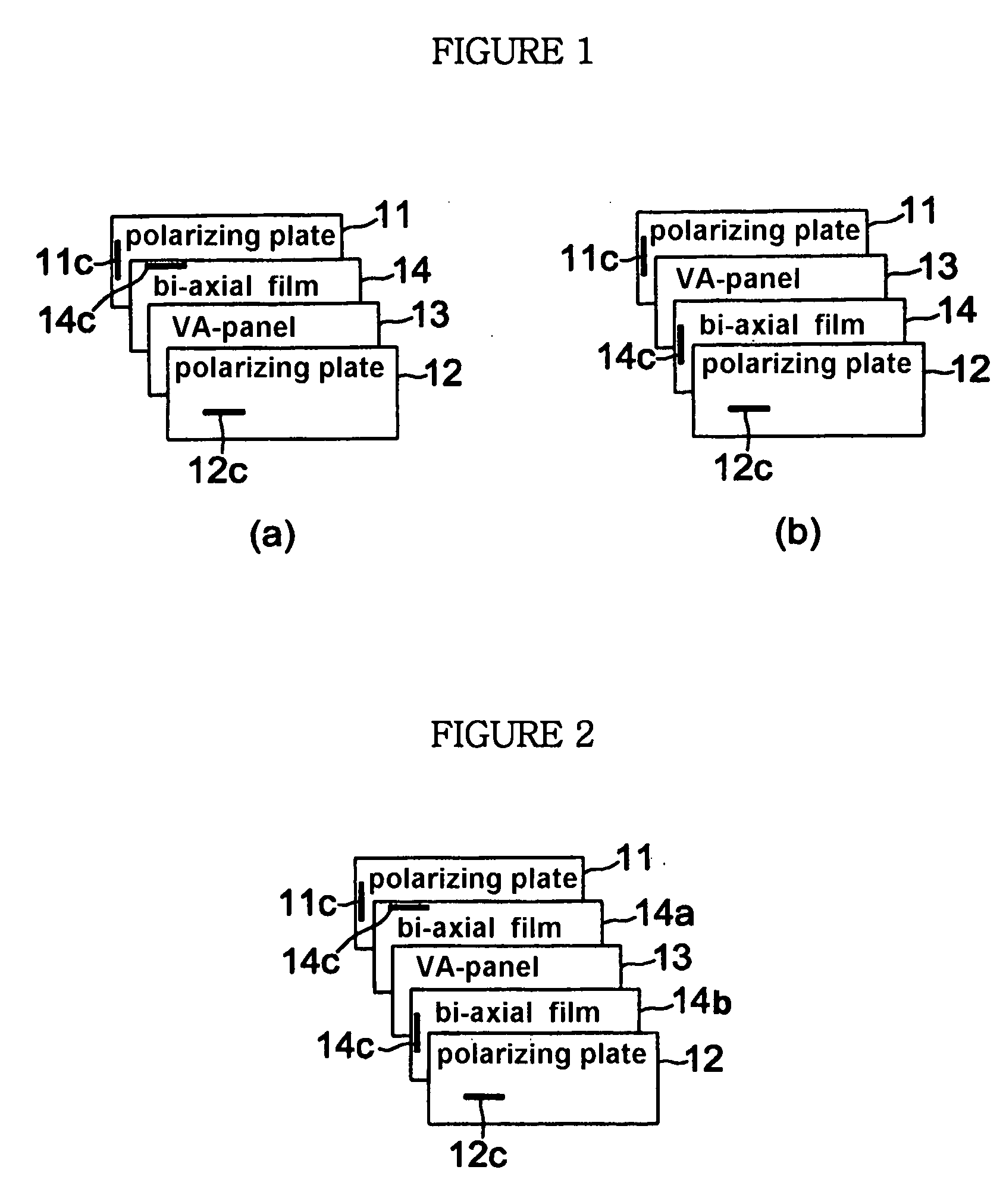
[0061] A VA-LCD was prepared by arranging one of a bi-axial retardation compensation film 14 between a vertically aligned panel 13 and upper and lower polarizing plates 11, 12 which are perpendicular to each other so that a cell gap of 3˜8 μm is maintained.
[0062]FIG. 1a illustrates an essential form of Example 1, in which a bi-axial retardation compensation film 14 is arranged between a vertically aligned panel 13 and a lower polarizing plate 11, wherein an optical axis 14c of the bi-axial retardation compensation film 14 is placed to be perpendicular to the an absorption axis 11c of the lower polarizing plate 11.
[0063]FIG. 1b illustrates other modified example of Example 1, in which a bi-axial retardation compensation film 14 is arranged between a vertically aligned panel 13 and a upper polarizing plate 12, wherein an optical axis 14c of the bi-axial retardation compensation film 14 is placed to be perpendicular to the an absorption axis 12c of the upper polarizing plate 12.
example 2
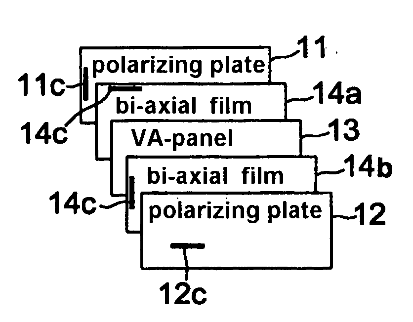
[0064] A VA-LCD as shown in FIG. 2 was prepared by arranging two of bi-axial retardation compensation films 14a, 14b between two of upper and lower polarizing plates 11, 12 which are perpendicular to a vertically aligned panel 13 so that a cell gap of 3˜8 μm is maintained.
[0065] Namely, two of bi-axial retardation compensation film was employed in this Example 2, in which one of the bi-axial retardation compensation film 14a is placed between a vertically aligned panel 13 and a lower polarizing plate 11, and another bi-axial retardation compensation film 14b is placed between a vertically aligned panel 13 and a upper polarizing plate 12, wherein an optical axis 14c of the bi-axial retardation compensation film 14a, placed between the vertically aligned panel 13 and the lower polarizing plate 11, is arranged to be perpendicular to an absorption axis 11c of the lower polarizing plate 11, and an optical axis 14c of the bi-axial retardation compensation film 14b, placed between the ver...
experimental example 1
[0067] A VA-LCD of FIG. 1(a) applying one of a bi-axial retardation compensation film prepared by Example 1 was used as a sample in this Experimental Example.
[0068] The VA-LCD included a VA-panel having a cell gap of 3 μm, wherein a pretilt angle was 89°, a dielectric anisotropy (Δε) was −4.9, a refractive anisotropy (Δn) was 0.0979, and a wavelength dispersion (Δn400 / Δn550) was 1.096. Accordingly, a thickness retardation (RVA,550) of the VA-panel at a wavelength of 550 nm was 297 nm.
[0069] The bi-axial retardation compensation film was prepared with polycarbonate series, wherein a thickness retardation value (Rth(550 nm)) was −270 nm, a in-plain retardation value (Rin(550 nm)) was 67 nm, a wavelength dispersion of a thickness retardation (Rth(450 nm) / Rth(550 nm)) was 1.15, and a wavelength dispersion of a in-plain retardation. (Rin(450 nm) / Rin(550 nm)) was 0.652.
[0070]FIG. 8 shows the result of simulation of a contrast ratio of the VA-LCD compensated by employing the above bi-ax...
PUM
 Abstract
Description
Claims
Application Information
 - R&D
- Intellectual Property
- Life Sciences
- Materials
- Tech Scout
- Unparalleled Data Quality
- Higher Quality Content
- 60% Fewer Hallucinations
Browse by: Latest US Patents, China's latest patents, Technical Efficacy Thesaurus, Application Domain, Technology Topic, Popular Technical Reports.
© 2025 PatSnap. All rights reserved.Legal|Privacy policy|Modern Slavery Act Transparency Statement|Sitemap|About US| Contact US: help@patsnap.com


