
Pelvic brace

a technology for pelvis and pelvic nerves, applied in non-surgical orthopedic devices, medical science, orthopedic corsets, etc., can solve the problems of 3 to 6 litres of blood loss into the pelvis region, serious life-threatening condition, and inability to carry out surgical procedures at accident scen

Inactive Publication Date: 2006-06-22
RICHARDSON MARTIN
View PDF3 Cites 21 Cited by
  • Summary
  • Abstract
  • Description
  • Claims
  • Application Information

AI Technical Summary

Benefits of technology

"The present invention provides a device for bracing the pelvic region of a patient that includes a plurality of straps for wrapping around the pelvic region of a patient. The straps are interconnected at points of relative movement, allowing for adjustable pressure and access to different areas of the patient. The device also includes fastening means for holding the straps in place on the patient. The straps can be adjusted in length to fit patients of varying sizes and the pressure applied by the straps can be adjusted as well. The device provides a convenient and effective way to support a patient during surgery or other medical procedures."

Problems solved by technology

The combination of a broken pelvic bone and ruptured blood vessels can result in up to 3 to 6 litres of blood loss into the pelvic region.
Blood loss of this magnitude is a serious life threatening condition.
Although advanced surgical procedures have been developed to repair ruptured blood vessels, it is not practical for these surgical procedures to be carried out at an accident scene or on route to a hospital.
Problems with this technique include firstly, it can be time consuming to apply and secondly, it may require the sheet to be maneuvered beneath a patient, which is usually not possible if the patient is suspected to have also sustained head, neck or spinal injuries.
Therefore, although the configuration of the device enables it to effectively apply positive pressure to the pelvic region, it may inhibit the treatment of other injuries.

Method used


Image

  • Pelvic brace
  • Pelvic brace
  • Pelvic brace

Examples


Embodiment Construction

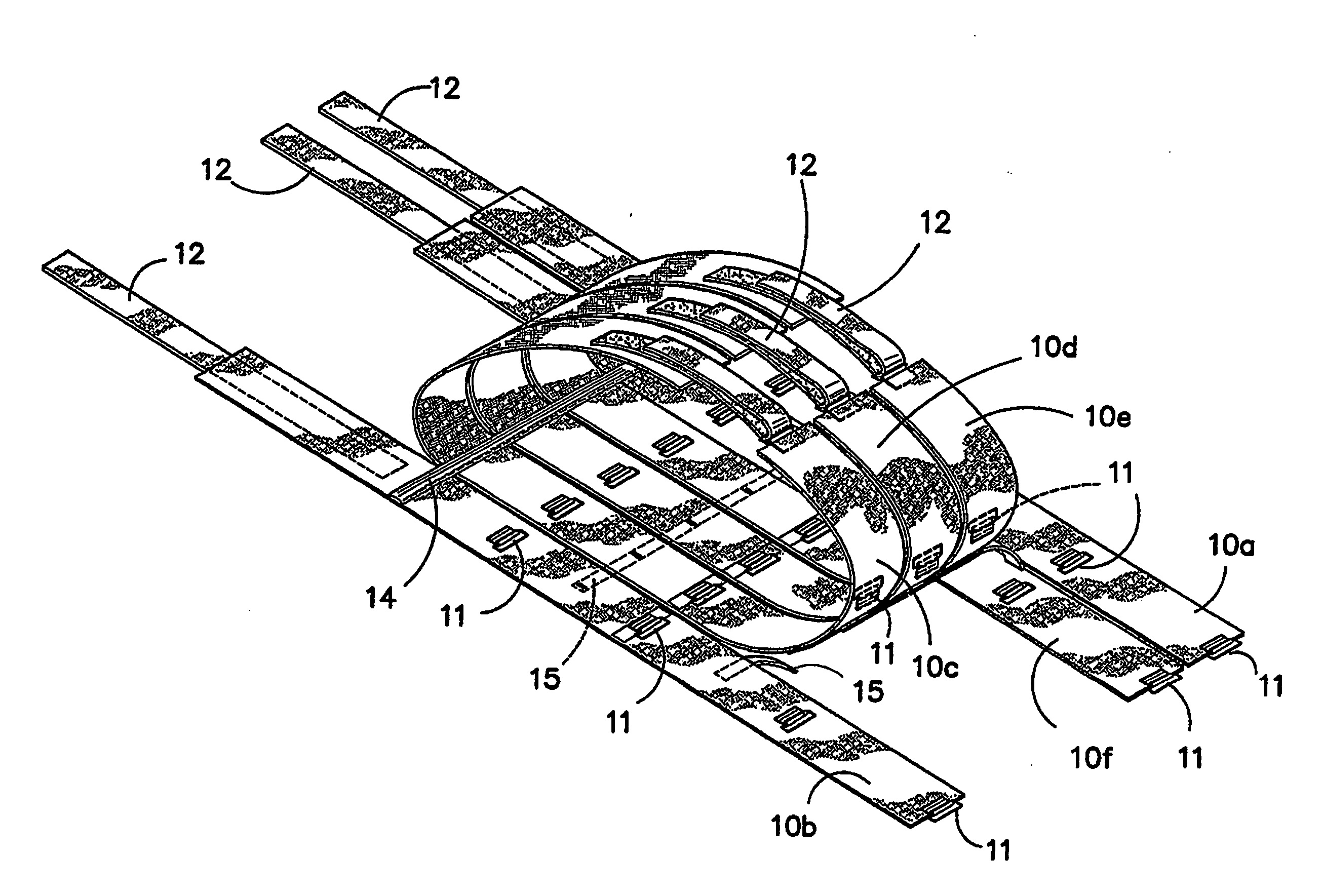
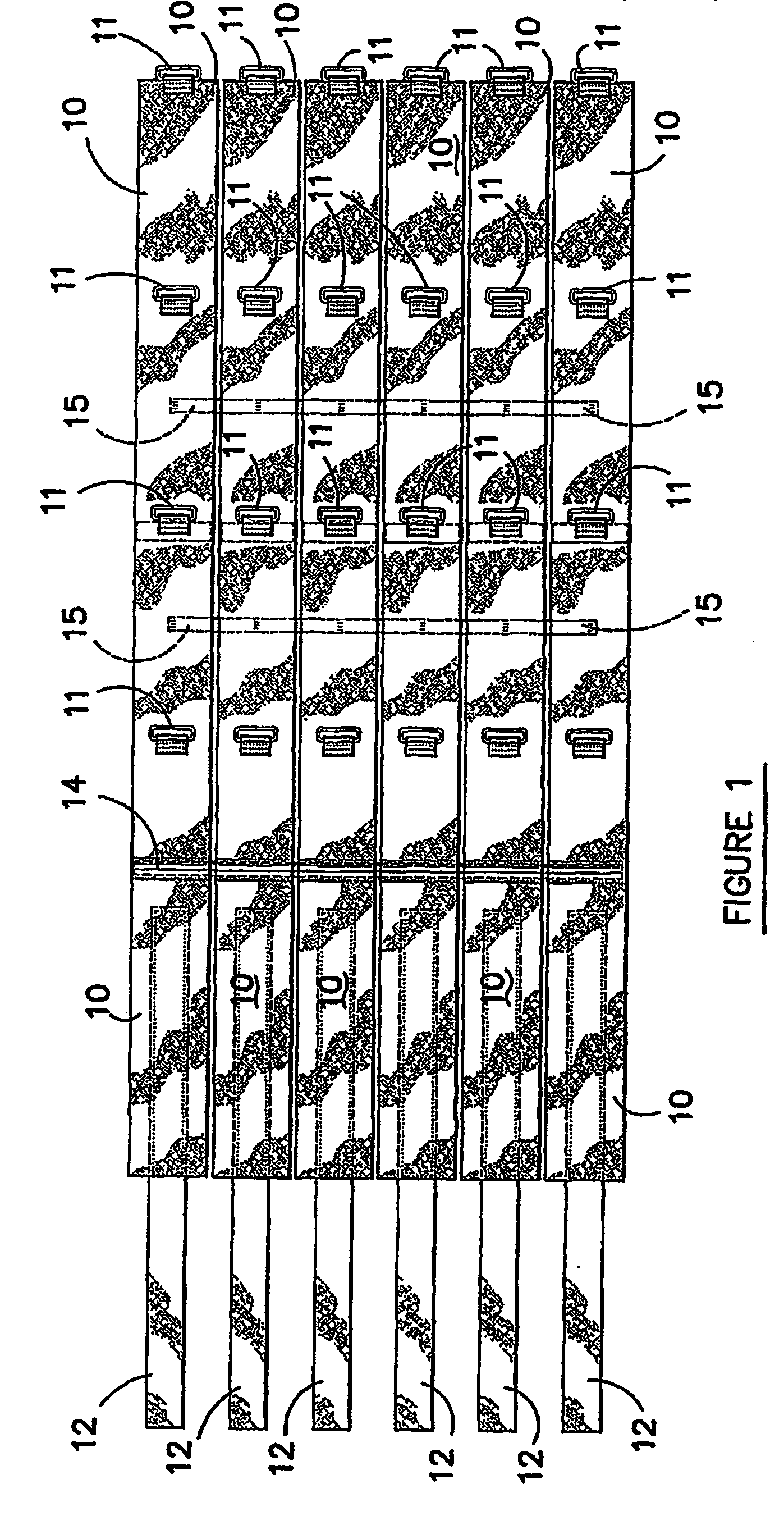
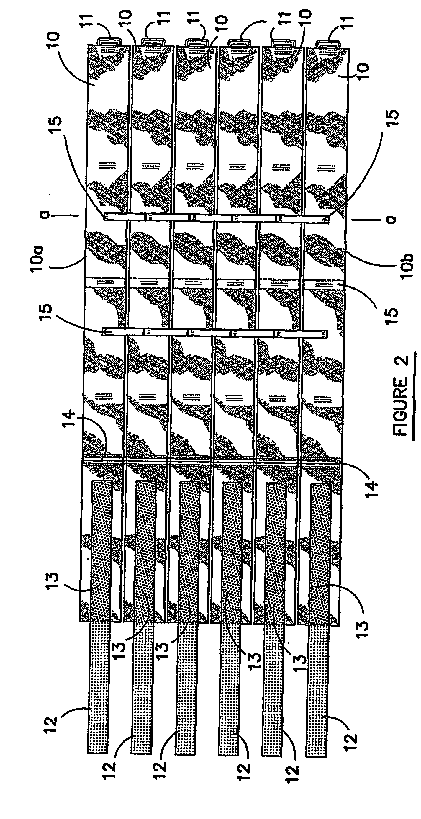
[0030] The brace according to the preferred embodiment includes six straps generally identified by reference numeral 10 arranged in a side-by-side relationship. Each strap 10 is substantially equal in length and has a fastening means for securing each strap in a wrapped orientation around the pelvic region of a patient. Each strap 10 is made from a highly elastic material and is approximately 10cm wide in an unstretched condition.

[0031] As can best be seen in FIGS. 1, 4 and 5, the fastening means includes a series of D-shaped rings 11 projecting from the front face of each strap 10, and hook and loop fasteners at one end of each strap 10. The hook and loop fasteners are constituted by two separate sections, wherein one section is in the form of a flexible tab 12 that projects from the straps 10 and the other section is a panel 13 sewn in a fixed position over an adjacent portion of the strap 10. Both the tabs 12 and fixed panels 13 have either hook or loop formations that face down...


PUM


Abstract

A device for bracing the pelvic region of a patient including plurality of straps for wrapping around the pelvic region of a patient is disclosed. The straps are arranged in a side-by-side relationship and interconnected to each adjacent strap at one or more points to restrict relative movement of the straps at each point of interconnection. When positioned on the patient, one of the straps may be an upper strap covering the upper pelvic region and adjoining lower abdominal region of a patient and the other strap or one of the other straps may be a lower strap covering the lower pelvic region and adjoining crutch region of the patient. Fasteners for holding the straps wrapped around the pelvic region of the patient are also included. In use, the fasteners of the upper strap can be released to provide access to the lower abdominal region, or the fasteners of the lower strap can be released to provide access to the crutch region of the patient.

Description

FIELD OF THE INVENTION [0001] The present invention relates to a device for bracing the pelvic region of a patient. BACKGROUND OF THE INVENTION [0002] Casualties of high impact accidents sometimes sustain a fractured or broken pelvis or pelvic bones. One of the many consequences that can occur from a broken pelvic bone is internal bleeding from ruptured blood veins and arteries passing through the pelvic region, such as those conveying blood to or from a patient's legs. The combination of a broken pelvic bone and ruptured blood vessels can result in up to 3 to 6 litres of blood loss into the pelvic region. Blood loss of this magnitude is a serious life threatening condition. [0003] Although advanced surgical procedures have been developed to repair ruptured blood vessels, it is not practical for these surgical procedures to be carried out at an accident scene or on route to a hospital. Paramedics and emergency hospital staff are therefore trained to identify internal bleeding caused...

Claims


Application Information

Patent Timeline
Patent Type & Authority Applications(United States)
IPC IPC(8): A61F5/00A61F5/02
CPCA61F5/028
Inventor RICHARDSON, MARTIN
Owner RICHARDSON MARTIN
Learn More