Optical system having extended angular scan range

a technology of optical system and angular scan, which is applied in the field of optical system with extended angular scan range, can solve the problems of limited laser printer print rate, speed at which the mirror can be rotated, and inability to meet the needs of optical elements,

Active Publication Date: 2006-06-29
AVAGO TECH INT SALES PTE LTD
View PDF7 Cites 34 Cited by
  • Summary
  • Abstract
  • Description
  • Claims
  • Application Information

AI Technical Summary

Benefits of technology

[0004] In accordance with the invention, a system and method for scanning light across a light-receiving surface is provided. A system for scanning light across a light-receiving surface to project a scanned line on the light-receiving surface has a light beam generator for generating a plurality of light beams. A scanning ...

Problems solved by technology

The speed at which the mirror can be rotated, and, accordingly, the print rate of t...

Method used


Image

  • Optical system having extended angular scan range
  • Optical system having extended angular scan range
  • Optical system having extended angular scan range

Examples


Embodiment Construction

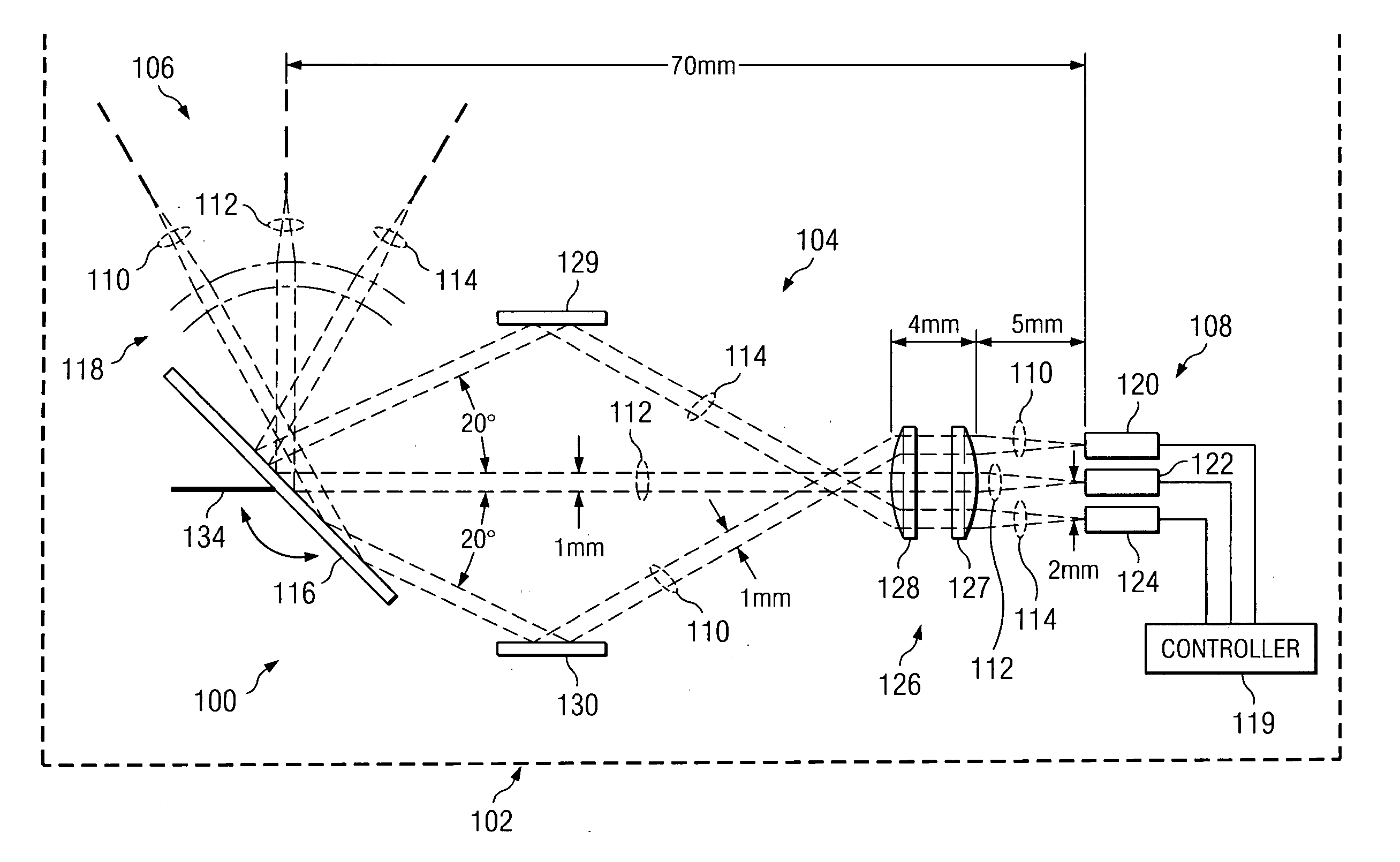
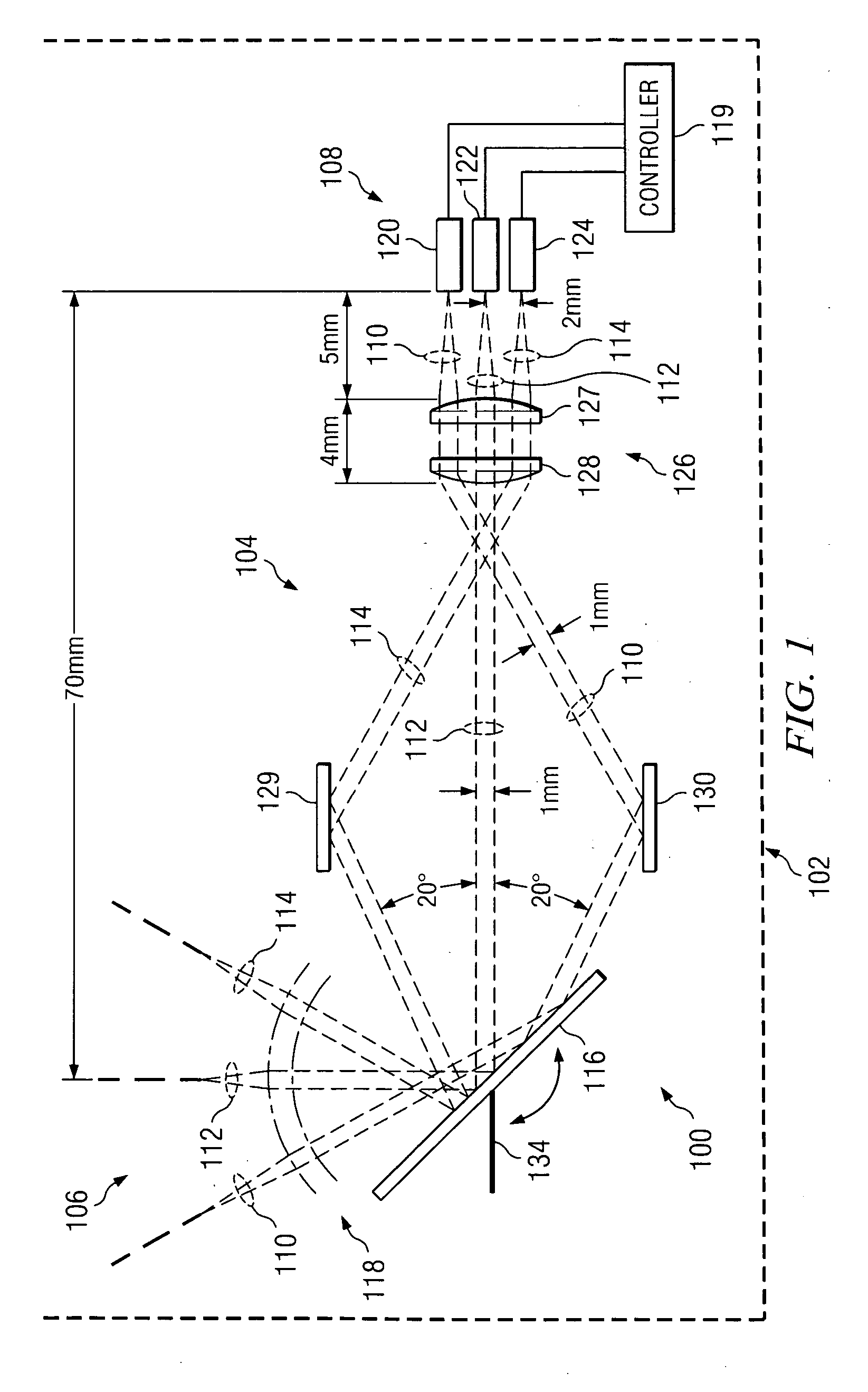
[0011] Embodiments in accordance with the invention provide an optical scanning system and method for scanning light across a light-receiving surface to project a scanned line on the light-receiving surface.

[0012]FIG. 1 schematically illustrates an optical scanning system according to an exemplary embodiment in accordance with the invention. The optical scanning system is generally designated by reference number 100, and in the exemplary embodiment described herein, comprises a laser print engine for a laser printer schematically illustrated at 102. It should be understood, however, that an optical scanning system in accordance with the invention is not limited to use in a laser printer, but can also be used in other optical scanning applications.

[0013] Optical scanning system 100 includes source assembly 104 and focusing assembly 106. Source assembly 104 includes light beam generator 108 for generating a plurality of light beams 110, 112 and 114, scanning mechanism 116, and optic...


PUM


Abstract

System and method for scanning light across a light-receiving surface. A system for scanning light across a light-receiving surface to project a scanned line on the light-receiving surface has a light beam generator for generating a plurality of light beams. A scanning mechanism simultaneously scans each light beam of the plurality of light beams across the light-receiving surface to project a different portion of the scanned line on the light-receiving surface. The scanning system can be utilized in a compact laser printer capable of printing at a high rate, and in other scanning applications.

Description

DESCRIPTION OF RELATED ART [0001] Laser printers transform electronically stored information into a “hardcopy” form that enables visual inspection and physical storage of the information. Current laser printers are capable of printing at a rate of about 16,000 lines per minute. Efforts are underway, however, to develop a “next generation” laser printer that is capable of printing at a rate of 32,000 lines per minute or more. [0002] Current laser printer technology is based on a laser printer engine that includes an edge emitting laser diode, a rotating mirror and refractive lenses. The rotating mirror scans a reflected laser beam across the width of a revolving drum. The laser beam alters the electrical charge on the drum surface wherever it strikes the surface. The drum is then passed through a toner reservoir so that toner is picked up by the charged portions on the drum surface, and the toner is then transferred from the drum to a sheet of paper by a combination of heat and press...

Claims


Application Information

Patent Timeline
IPC IPC(8): G02B26/08
CPCG02B26/0833G02B26/123Y10S359/904
Inventor GRUHLKE, RUSSELL W.MATTA, FARID
Owner AVAGO TECH INT SALES PTE LTD
Why Eureka
Try Eureka