Color management system

a color management system and color management technology, applied in the direction of display means, electric devices, transportation and packaging, etc., can solve the problems of increasing the cost and complexity of light sources, increasing the cost of light sources, and affecting the output of individual leds

Inactive Publication Date: 2006-06-29
AVAGO TECH INT SALES PTE LTD
View PDF4 Cites 7 Cited by
  • Summary
  • Abstract
  • Description
  • Claims
  • Application Information

AI Technical Summary

Problems solved by technology

Unfortunately, the output of the individual LEDs varies with age.
Unfortunately, such feedback systems substantially increase the cost and complexity of the light source.
However, these filters add to the cost of the light source.
In such systems, additional light isolation systems must be utilized that further increase the cost and complexity of the systems.

Method used


Image

  • Color management system
  • Color management system
  • Color management system

Examples


Embodiment Construction

[0009] The present invention is based on the observation that the decrease in light output over time can be approximated by a linear function of the operating parameters of the LED, and hence, can be predicted if the relevant calibration constants are known for the LEDs in question. As the device ages, the drive current can then be increased to a value that depends on the age of the device, and hence, at least a partial correction for the aging effects can be obtained without the high cost and complexity associated with feedback systems.

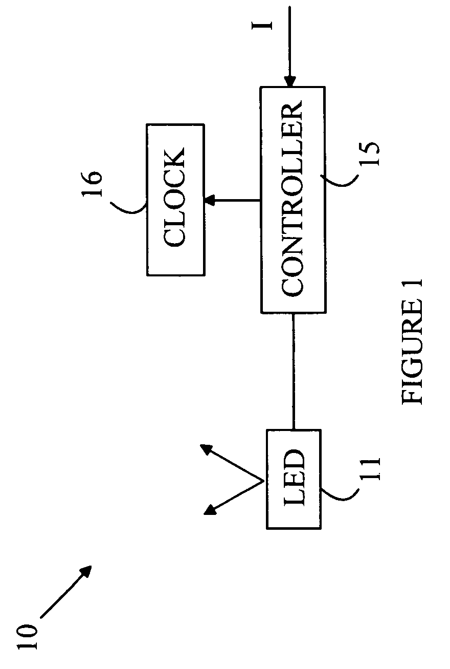
[0010] Refer now to FIG. 1, which illustrates a light source 10 according to one embodiment of the present invention. Light source 10 includes an LED 11 and a controller 15 that sets the drive current through LED 11. Controller 15 receives an input signal specifying the desired light output from LED 11. For the purposes of this discussion, it will be assumed that the intensity of light from LED 11 is controlled by controlling the duty factor of an o...


PUM


Abstract

A light source and a method for operating the same are disclosed. The light source includes a light emitter and a controller. The light emitter generates light in response to a control signal coupled thereto. The light emitter is characterized by an age related to the amount of light that has been cumulatively generated by the light emitter, the generated light for a given control signal changing with the age. The controller measures the age of the light emitter and generates the control signal based on the desired light intensity and the measured age of the light emitter. In one embodiment, the controller stores an age value for the light emitter, and the controller determines the control signal in response to an input signal specifying a desired light intensity from the light emitter, the controller updating the age value each time the control signal is determined.

Description

BACKGROUND OF THE INVENTION [0001] Light emitting diodes (LEDs) are attractive candidates for replacing conventional light sources such as incandescent lamps and fluorescent light sources. The LEDs have higher light conversion efficiencies and longer lifetimes. Unfortunately, LEDs produce light in a relatively narrow spectral band. Hence, to produce a light source having an arbitrary color, a compound light source having multiple LEDs is typically utilized. For example, an LED-based light source that provides an emission that is perceived as matching a particular color can be constructed by combining light from red, green, and blue emitting LEDs. The ratio of the intensities of the various colors sets the color of the light as perceived by a human observer. [0002] The intensity of the LED can be varied by varying the drive current or the duty factor. In duty factor schemes, the LED is pulsed on a time scale that is too fast to be seen by a human observer. During each cycle, the LED ...

Claims


Application Information

Patent Timeline
Patent Type & Authority Applications(United States)
IPC IPC(8): B60Q1/26
CPCH05B33/086H05B33/0869Y10S362/80H05B45/22H05B45/20
Inventor YOGANANDAN, SUNDAR NATARAJANMOK, THYE LINNLEE, KIAN SHINKARIM, NORFIDATHUL AIZAR ABDULOON, SU LINPANG, SIEW ITTAN, KHENG LENGAFIF, FAKHRUL ARIFIN MOHDOU, WEN YAKUAN, YEW CHEONG
Owner AVAGO TECH INT SALES PTE LTD
Why Eureka
Try Eureka