Pulley assembly

a technology of flanges and flanges, which is applied in the direction of gearing, hoisting equipment, gearing elements, etc., can solve the problems of loose bearings, wobbly hubs, and loose bearings when crimping each of the flanges in two separate operations

Inactive Publication Date: 2006-06-29
RADOCAJ MIJO
View PDF14 Cites 27 Cited by
  • Summary
  • Abstract
  • Description
  • Claims
  • Application Information

AI Technical Summary

Benefits of technology

[0008] Another object of the invention is to provide a method for rapidly inserting and fastening a bearing within a hub of a pulley without the need of pr

Problems solved by technology

It has been found, however, that crimping each of the flanges in two separate operations does not provide as tight a fit around the bearing as when the flanges are crimped simultaneously after press fitting the bearing into the hub, since there is less area of surface contact between the hub and the b

Method used


Image

  • Pulley assembly
  • Pulley assembly
  • Pulley assembly

Examples


Embodiment Construction

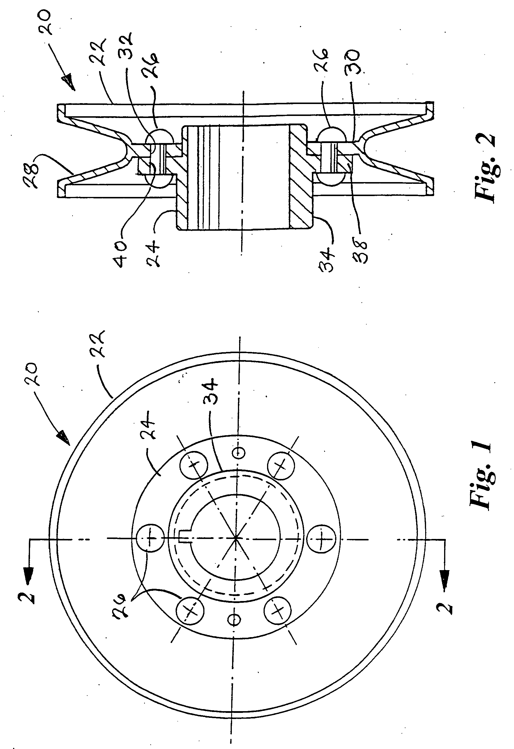
[0020] Referring to the drawings and in particular to FIGS. 1 and 2, a pulley assembly indicated by the numeral 20 has a pulley 22 and a hub 24 fastened together by rivets 26.

[0021] The pulley has a belt groove 28 extending around the outer periphery thereof and an annular web portion 30 extending radially inwardly from the belt groove 28. The web portion 30 has a plurality of space apart holes 32 located around the web and extending transversely therethrough.

[0022] The hub 24 has an annular body portion 34 and an annular extension flange 38 projecting radially outwardly to overlay and lie adjacent the web 30 when the hub and pulley are assembled together. The flange 38 has a plurality of holes 40 which are spaced to correspond to the holes 32 in the pulley web 30 to permit the rivets 26 to pass through the flange 38 and web 30 and fasten together the pulley and hub.

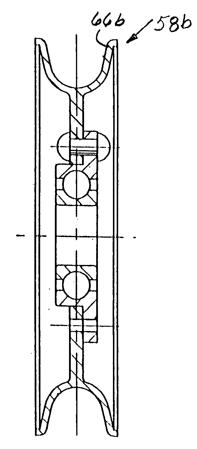
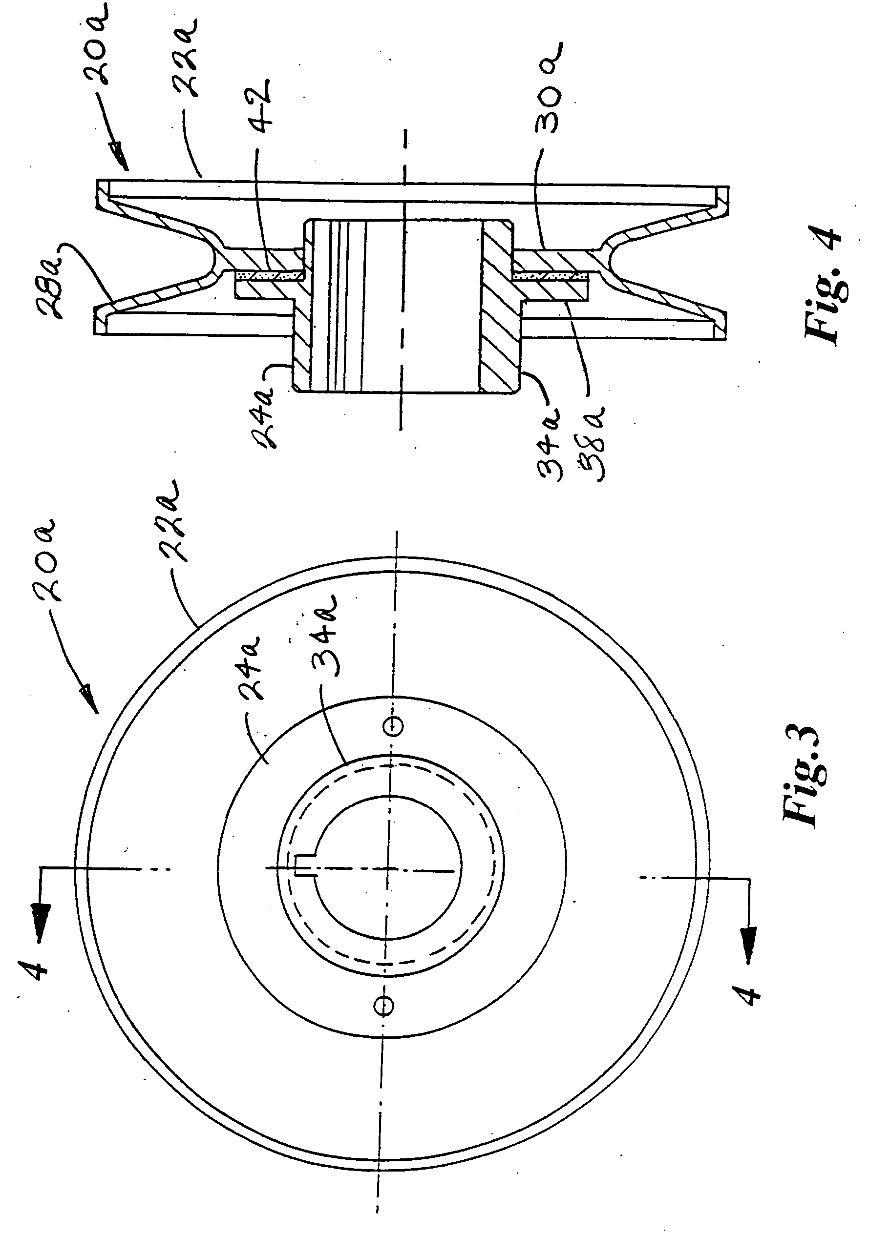
[0023] Referring now to FIGS. 3 and 4, a pulley assembly 20a is similar to the pulley assembly 20 except that inste...


PUM


Abstract

A pulley assembly in which either a hub or a bearing is attached in the center of one or more pulleys either by rivets passing transversely through overlapping portions of the pulley and the hub or bearing. When fastening together a hub and a pulley, the pulley has belt groove around the outer periphery and an annual web extending radially inwardly from the belt groove. A hub has a radially outwardly extending flange which overlaps the web of the pulley and in one embodiment a plurality of rivets pass through matching holes in the pulley web and the hub flange to fasten the hub and pulley together instead of using rivets, the pulley web and hub may be fastened together either with an adhesive layer or by friction welding of adjacent surfaces of the pulley web and the hub flange. When attaching bearings to a pulley an annular flange extends radially outwardly from the outer race of the bearing and overlaps a radially inwardly extending web of a pulley. The pulley and bearing can be fastened together either by rivets passing transversely through the pulley web and bearing flange or by applying a layer of adhesive between adjacent surfaces of the pulley web and bearing flange.

Description

FIELD OF THE INVENTION [0001] This invention relates generally to a pulley assembly in which a bearing or a hub is fastened in the axial center of the bearing and in particular to fastening the bearing or hub is fastened by means of a plurality of rivets or alternatively by an adhesive or by friction welding. BACKGROUND OF THE INVENTION [0002] In the past is has been known to fasten two piece pulleys together on each side of a bearing to hold the bearing in place. One such example is shown in U.S. Pat. No. 4,518,372 issued to Donald D Dye. [0003] Fastening a bearing or hub in a pulley made by splitting a disk and spin forming it into a pulley requires a different fastening configuration. [0004] Various means have been used in the past to fasten a bearing into the center flange of a pulley or other rotary object which has been formed by splitting a circular disk and spin forming the blank into a pulley shape. A separate bearing housing is then attached to the pulley by welding stakin...

Claims


Application Information

Patent Timeline
IPC IPC(8): F16H55/36F16H55/49F16H55/50
CPCF16H55/36F16H55/50
Inventor RADOCAJ, MIJO
Owner RADOCAJ MIJO
Why Eureka
Try Eureka