Hair iron

Active Publication Date: 2006-07-06
THE PROCTER & GAMBLE COMPANY +1
View PDF4 Cites 15 Cited by
  • Summary
  • Abstract
  • Description
  • Claims
  • Application Information

AI Technical Summary

Benefits of technology

[0005] The purpose of the present invention is to solve the aforementioned problems of the conventional methods by providing a hair iron that can generate

Problems solved by technology

Consequently, in the liquid holder, the liquid in the portion farther from the liquid container is more difficult to transfer, and

Method used


Image

  • Hair iron
  • Hair iron
  • Hair iron

Examples


Embodiment Construction

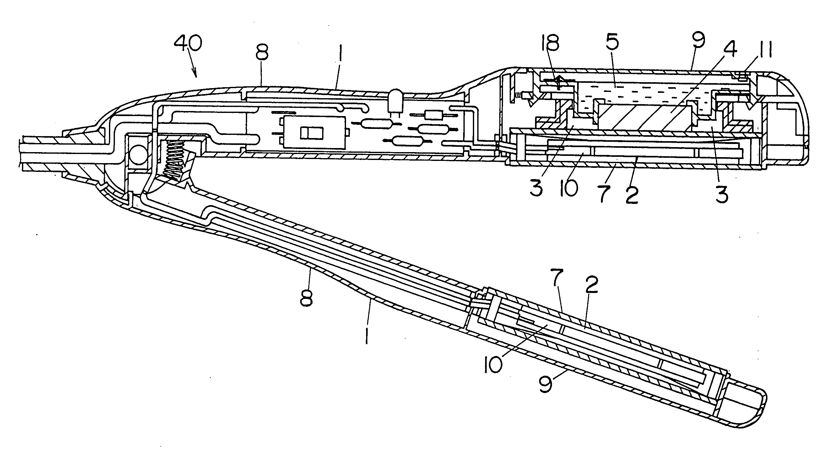
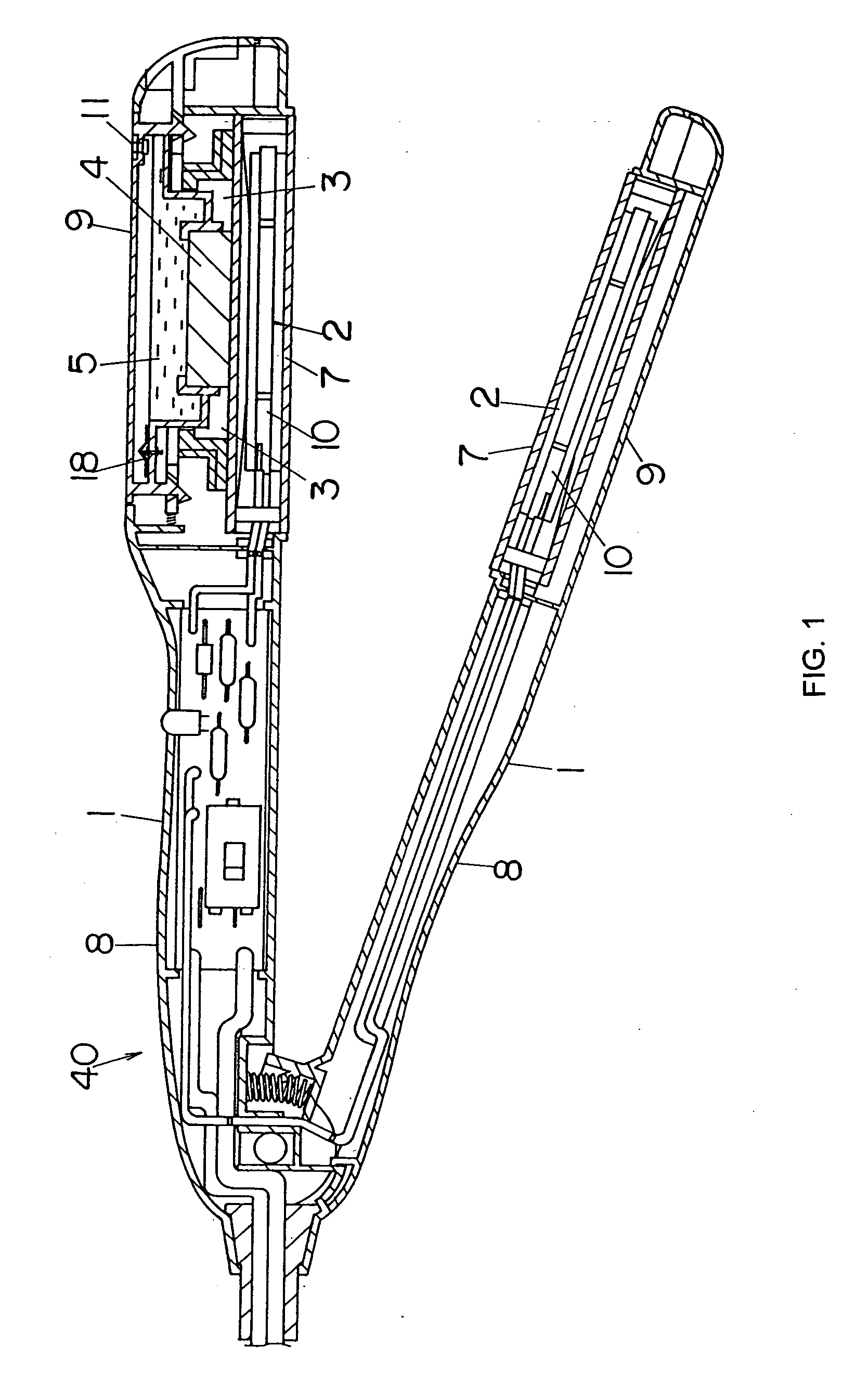
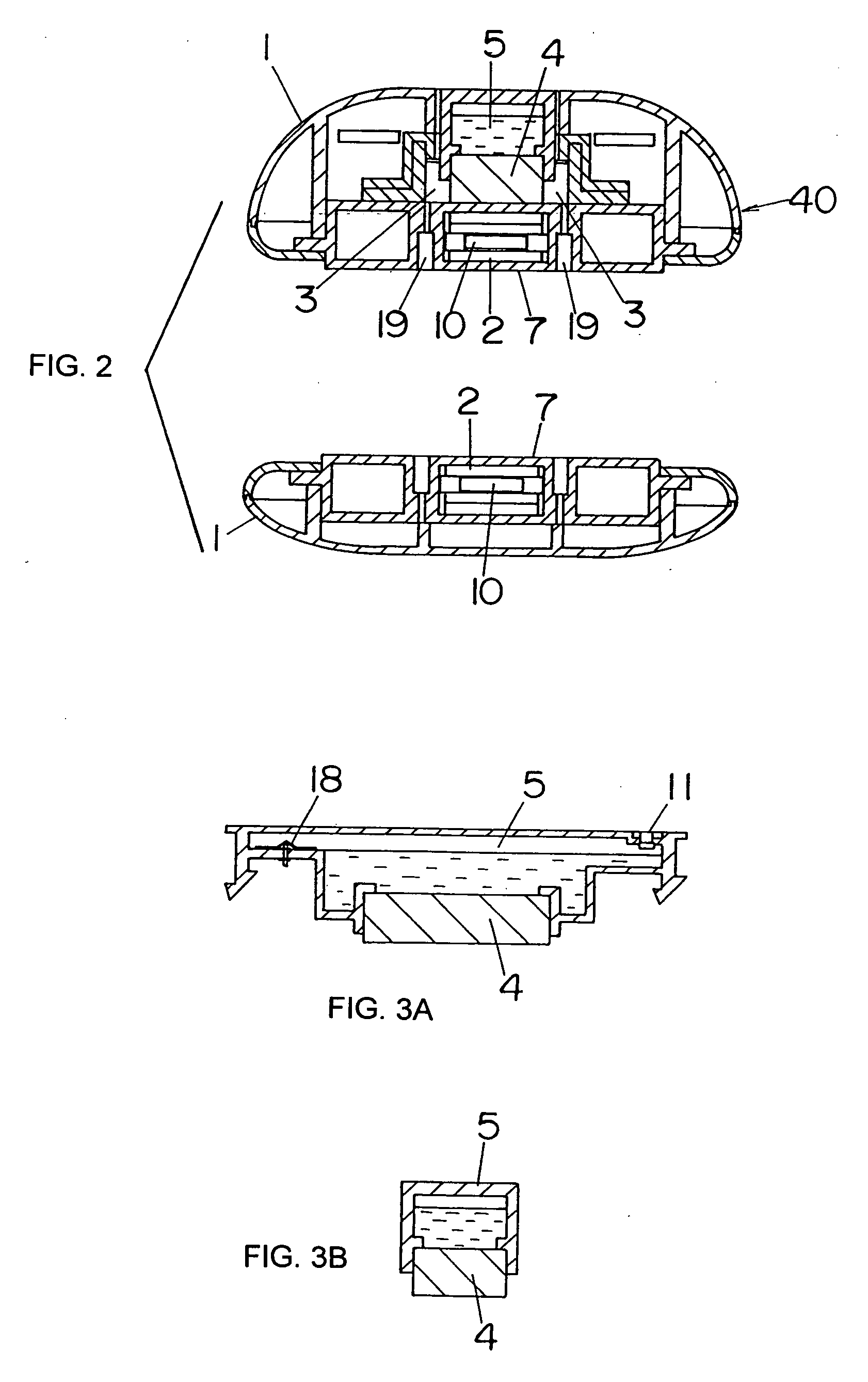
[0040] In the following, embodiments of the present invention will be explained with reference to figures. In an embodiment of the present invention, as shown in FIGS. 1 and 2, a hair iron (40) has its main body composed of a pair of holding parts (1, 1) which are in elongated shape and have their ends on one side in the longitudinal direction hinged together to form a V-shape that can be opened / closed at will. For two holding parts (1, 1), handle portions (8, 8) are formed on their ends on one side that are hinged, while holding portions (9, 9) are formed on the ends on the other side. The holding portion (9) contains a heating block (2) made of a heater (10) composed of a PTC element. The surface of the heating block (2) is exposed on the opposing surface of holding part (1), and it becomes a holding surface (7) with an elongated planar shape. Since the main body is V-shaped, it is possible to adjust the force for holding the hair between holding surfaces (7, 7) easily, and, by me...


PUM

PropertyMeasurementUnit
Poweraaaaaaaaaa
Viscosityaaaaaaaaaa
Dimensionaaaaaaaaaa

Abstract

A hair iron that can set hairstyles by heating and spraying a treatment agent comprises a pair of holding parts (1, 1); each having heating block (2), the surface of which acts as a holding surface (7); at least one holding part (1) containing liquid container (5), liquid holder (4) that brings the liquid in liquid container (5) in contact with heating block (2) as the liquid in liquid container (5) is transferred to heating block (2), and steam path (19) that sprays from holding surface (7) the steam generated as the liquid transferred from inside liquid container (5) is heated by the contact surface with heating block (2) of liquid holder (4). Hair is held between the holding surfaces (7, 7) of the pair of holding parts (1, 1), and under the action of the steam sprayed from the steam path (19), the hairstyle is set. In this hair iron (40), the liquid container (5) is set on the side of the heating block (2) opposite to the holding surface (7), and at the same time, the liquid holder (4) is set between the heating block (2) and the liquid container (5).

Description

TECHNICAL FIELD [0001] The present invention relates to a type of hair iron that sets hairstyles by heating and spraying a treatment agent. BACKGROUND ART [0002] Hair irons usually comprise a pair of holding parts that are equipped with heating blocks and that are hinged at one end, where at least one of the holding parts has a steam spraying means. The hair is held between the opposing surfaces of the pair of holding parts so that it can be set to the desired hairstyle with heat and steam. [0003] As described in Japanese Patent Early Publication [kokai] No. 2000-157322, etc., the conventional steam spraying means has a liquid container at the end of a holding part. One end of the liquid holder, such as a piece of felt, is in contact with the liquid in the liquid container, while the other end of the liquid holder is in contact with a heating block. In this constitution, the liquid that has been transferred by the liquid holder to the heating block evaporates, and steam is sprayed f...

Claims


Application Information

Patent Timeline
IPC IPC(8): A45D1/00A45D2/40A45D6/06A45D1/04A45D1/06A45D2/00A61K8/58A61K8/69A61Q5/06
CPCA45D1/04A45D1/06A45D2/001A45D2001/008A61K8/585A61K8/69A61Q5/06
Inventor CARBALLADA, JOSEAKUHLMAN, DENNISESTENTZ, DAVIDMNISHIMURA, SHINJINAKASAI, KAZUNORI
Owner THE PROCTER & GAMBLE COMPANY
Why Eureka
Try Eureka