Fan cowl door elimination

a technology of aircraft engine and fan cowl, which is applied in the direction of machines/engines, efficient propulsion technologies, power plant inspection panels, etc., can solve the problems of lifting systems and adding to the overall weight of aircraft, and achieve the effects of reducing the weight of the nacelle, enhancing fuel efficiency, and structural weight elements

Inactive Publication Date: 2006-07-06
THE BOEING CO
View PDF25 Cites 88 Cited by
  • Summary
  • Abstract
  • Description
  • Claims
  • Application Information

AI Technical Summary

Benefits of technology

[0005] The present invention provides for a nacelle for housing an aircraft jet engine. The jet engine has a fan case and a portion disposed downstream of the fan case relative to a direction of airflow through the jet engine. The nacelle comprises an inlet for receiving airflow, a fan cowl panel for covering a forward portion of the fan case, and a thrust reverser having a longitudinal length sufficient to cover the downstream portion of the jet engine in addition to a rearward portion of the fan case. Opening the thrust reverser enables access to an entire area formed by the downst...

Problems solved by technology

These lift systems add to t...

Method used


Image

  • Fan cowl door elimination
  • Fan cowl door elimination
  • Fan cowl door elimination

Examples


Embodiment Construction

[0026] The following description of the preferred embodiments is merely exemplary in nature and is in no way intended to limit the invention, its application, or uses.

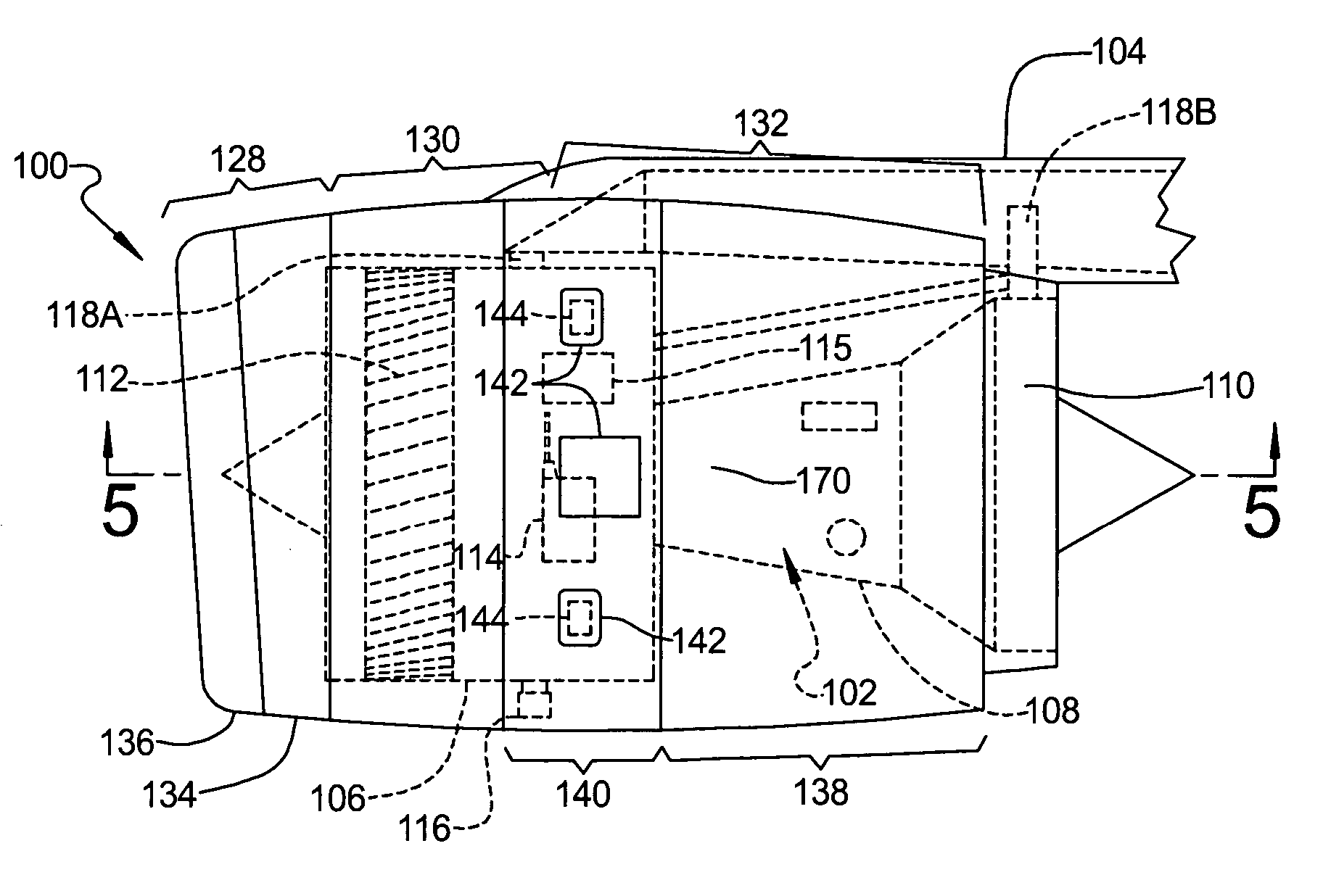
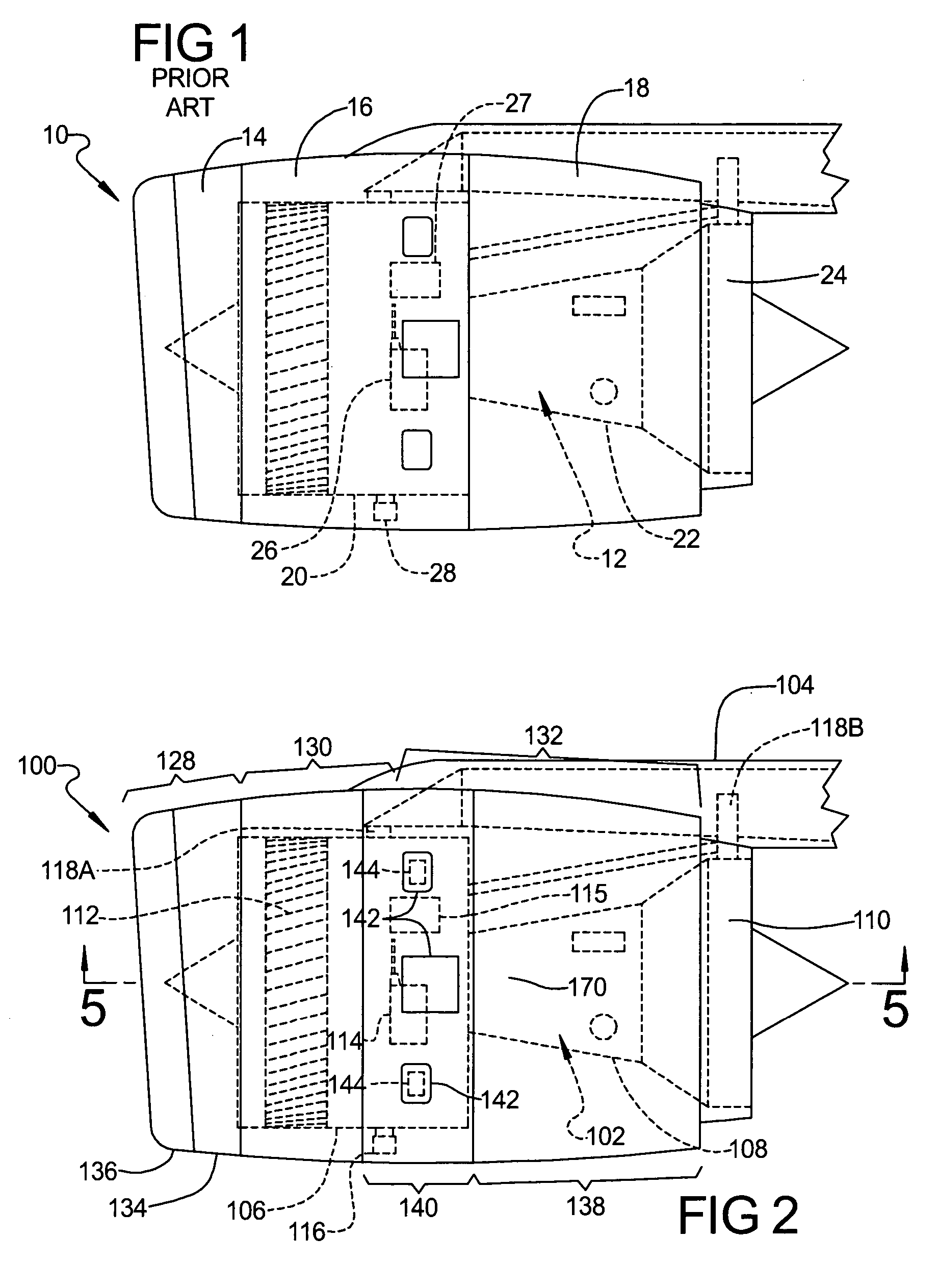
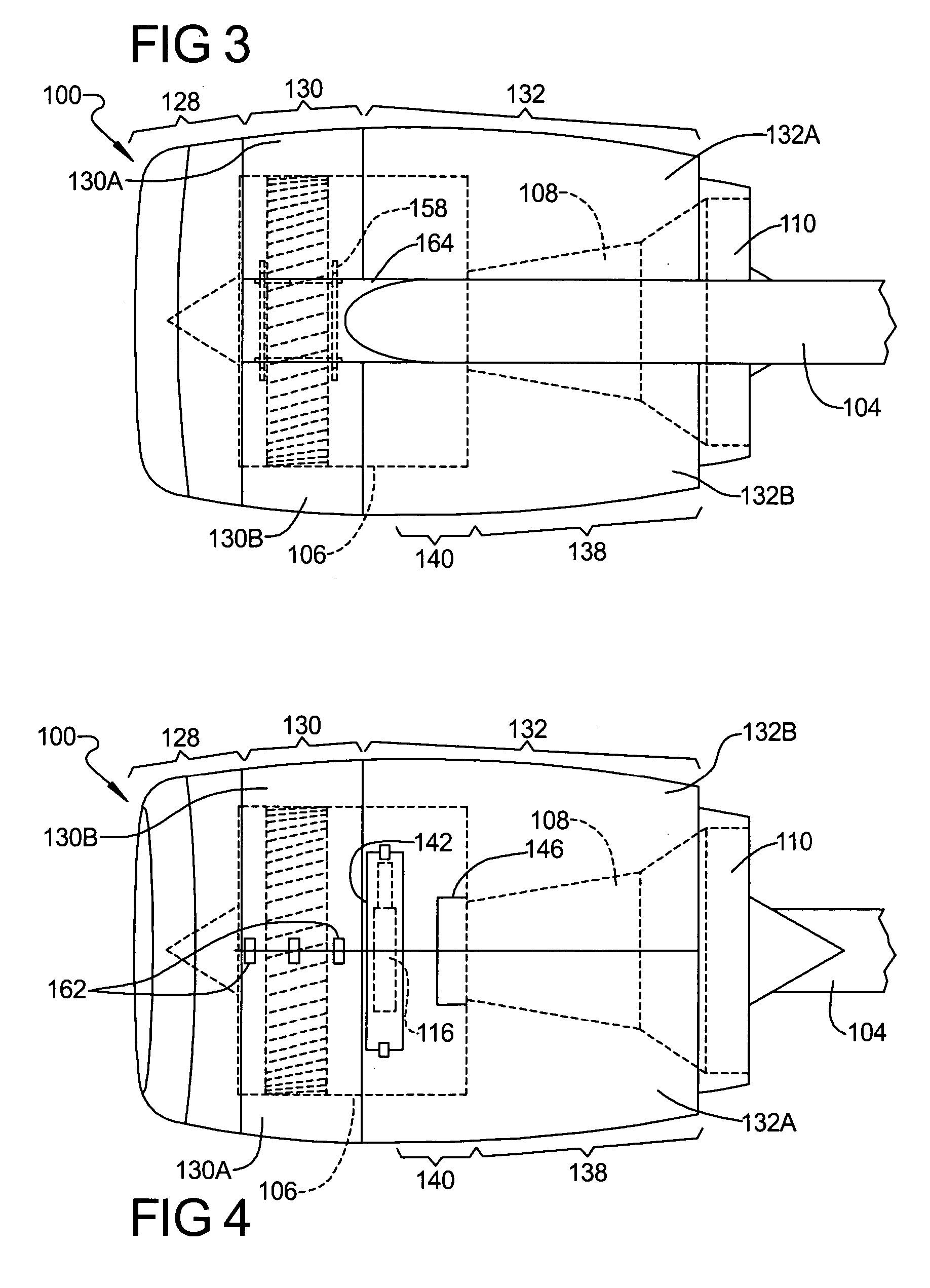
[0027] With initial reference to FIGS. 2 through 4, an aircraft engine nacelle 100 is shown. The nacelle 100 houses an aircraft engine 102. The nacelle 100 and the engine 102 are mounted to an aircraft (not shown) by a pylon or strut 104.

[0028] The engine 102 can be any conventional engine such as, for example, a high-bypass ratio aircraft engine. Typically, the engine 102 includes a fan case 106 and various components aft of the fan case 106, such as an engine core 108 including, for example, a nozzle 110. As described herein, “aft” is the right side of the engine 102 as viewed in the figures and “forward” is the left side. Further, the components aft of the fan case 106, such as the core 108, are downstream of the fan case 106 relative to a direction of airflow, which enters the engine 102 through the inlet 128 and...


PUM


Abstract

A nacelle for housing an aircraft jet engine. The jet engine has a fan case and a portion disposed downstream of the fan case relative to a direction of airflow through the jet engine. The nacelle comprises an inlet for receiving airflow, a fan cowl panel for covering a forward portion of the fan case, and a thrust reverser having a longitudinal length sufficient to cover the downstream portion of the jet engine in addition to a rearward portion of the fan case. Opening the thrust reverser enables access to an entire area formed by the downstream portion as well as the rearward portion of the fan case.

Description

FIELD OF THE INVENTION [0001] The present invention relates to aircraft engine nacelles. In particular, the present invention relates to an aircraft engine nacelle having a thrust reverser that overlaps a portion of an aircraft engine fan case. BACKGROUND OF THE INVENTION [0002] With reference to FIG. 1, a conventional aircraft engine nacelle is illustrated at 10. The nacelle 10 houses a conventional aircraft engine 12. The nacelle 10 generally includes an inlet cowl 14, a fan cowl panel 16, and a thrust reverser 18. The engine 12 generally includes a fan case 20 and various components aft of the fan case, such as an engine core 22 including a nozzle 24. The inlet cowl 14 surrounds an area forward of the fan case 20. The fan cowl 16 surrounds and covers the fan case 20. The thrust reverser 18 surrounds and covers the engine core 22. The thrust reverser 18 does not cover the fan case 20. [0003] Mounted to the fan case 20 are various components and devices of the engine 12, such as an...

Claims


Application Information

Patent Timeline
IPC IPC(8): F02K1/54
CPCB64D29/06B64D29/08B64D33/04F02K1/72F02K3/06Y02T50/671F05D2230/60F05D2230/70Y02T50/60
Inventor SMITH, MATTHEW C.
Owner THE BOEING CO
Why Eureka
Try Eureka