Eureka AIR delivers breakthrough ideas for toughest innovation challenges, trusted by R&D personnel around the world.

Frame components and frame for constructing picture displays

Inactive Publication Date: 2006-07-06
MARKETING DISPLAY
View PDF24 Cites 9 Cited by
  • Summary
  • Abstract
  • Description
  • Claims
  • Application Information

AI Technical Summary

Benefits of technology

[0007] The present invention provides a frame component, as well as a frame for constructing picture displays that enable a presentation of flexible sheet picture carriers or pictures that are essentially free of creases or wrinkles, and also enable an easy exchange of the picture carrier in the frame with another picture carrier.
[0009] With the present inventive approach, it is now possible to insure that the pivot position of the clamping frame element relative to the support frame element is at a fixed location. One thus has the possibility of subsequently tensioning the clamping frame relative to the support frame, and hence increasing the pressure the clamping frame exerts on the picture carrier to create tension in the picture carrier. The pivotal position of the clamping frame element can be controlled so that the picture carrier remains under a suitable tension, but remains undamaged.
[0020] The invention is advantageously used for a light box display with the frame of the light box formed from at least one of the frame element assemblies of the present invention. The frame element assembly, including the base or support frame element and the pivoting clamping element is very effective to provide a wrinkle free picture carrier, in a display frame, and yet is low cost.

Problems solved by technology

In particular for constructing large-surface displays, the picture carriers should be able to be presented in a manner that is as free of creases as possible and has a planar surface appearance but this is a problem with existing frames.
Although when clamping frames are used, spring elements are frequently disposed between support frame and clamping frame for pre-tensioning the clamping frame relative to the support frame, the spring forces are frequently inadequate to exert a sufficient pressure of the clamping frame upon the picture carrier in order to be able to present the latter in a manner free of creases.

Method used


Image

  • Frame components and frame for constructing picture displays
  • Frame components and frame for constructing picture displays
  • Frame components and frame for constructing picture displays

Examples


Embodiment Construction

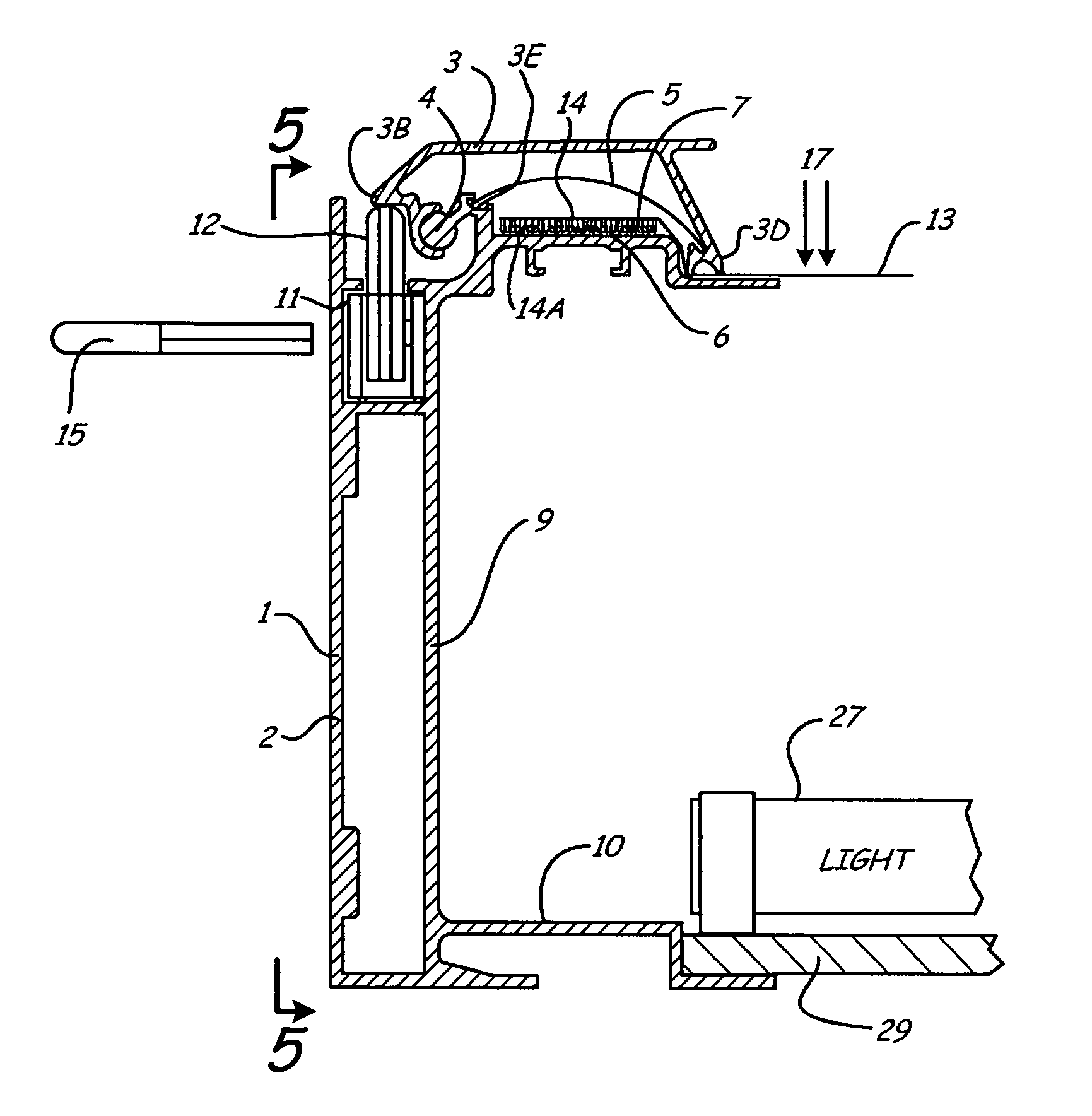
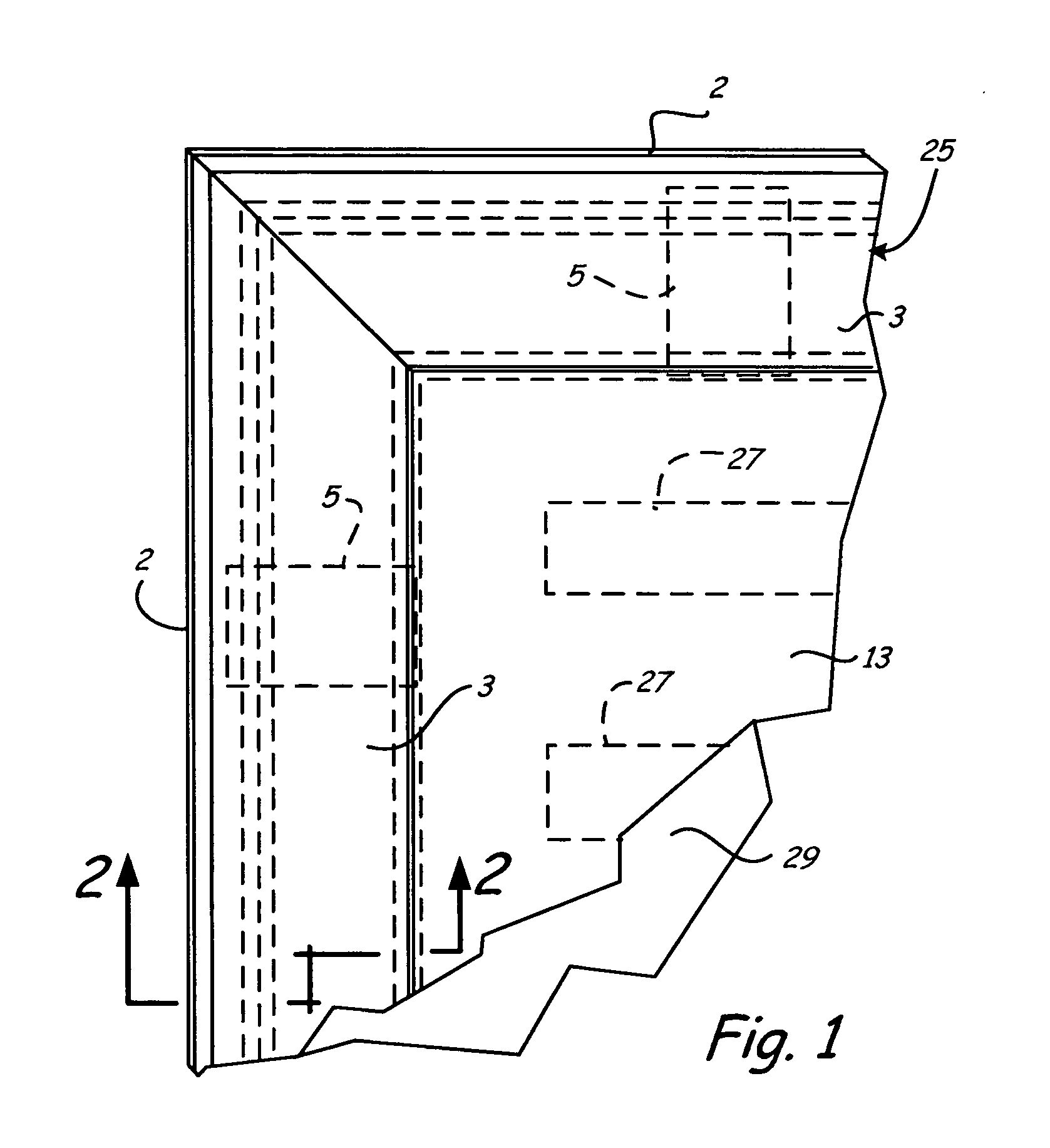
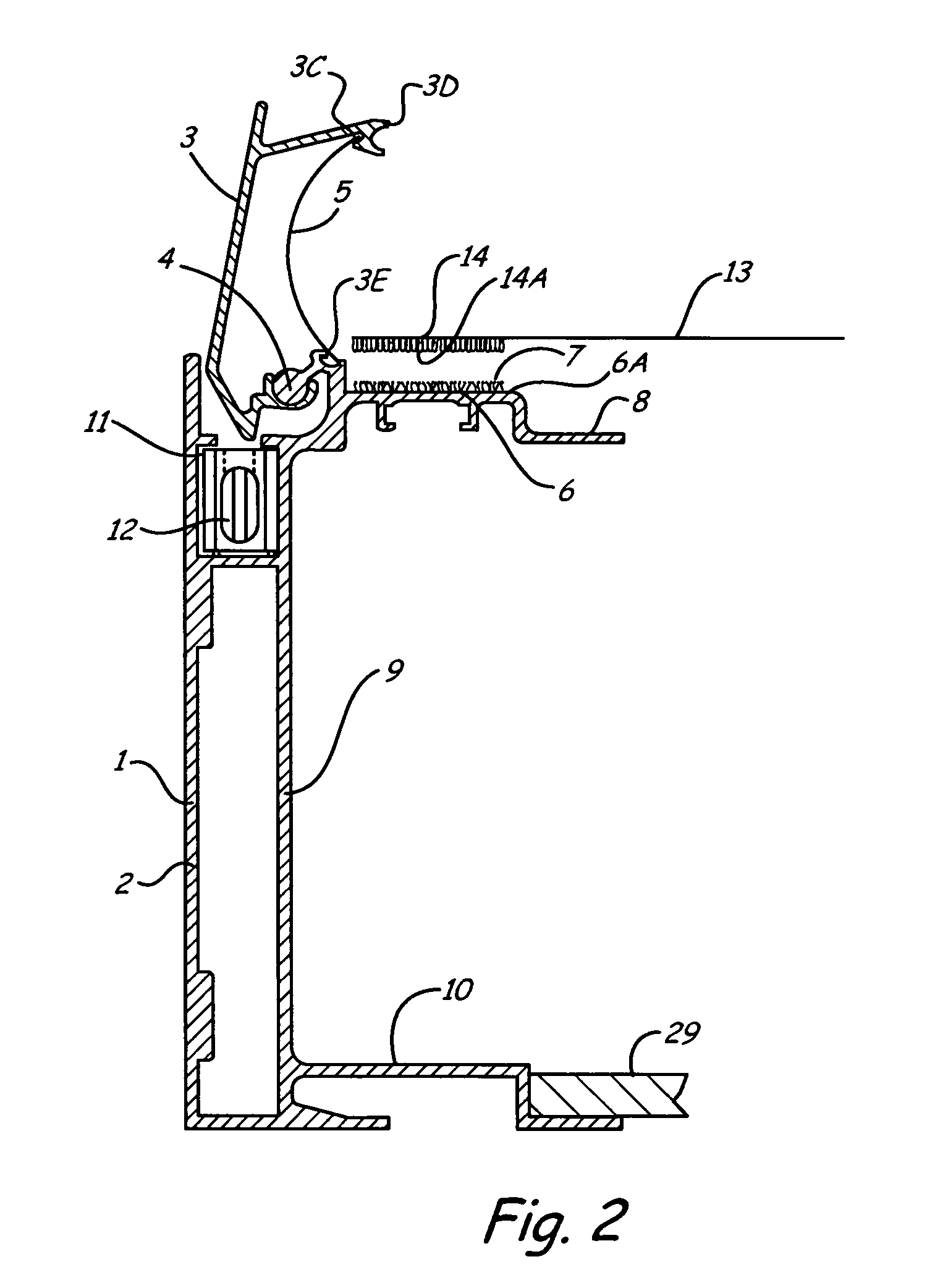
[0026] As shown in FIGS. 1-4, the frame element assembly 1 includes a base support frame element or member 2 and a clamping frame element or member 3. In this connection, the components can be extruded elements, for example of aluminum that can be anodized. However, the frame elements are formed in a specific profile, as shown, and can also be multi-sectional and can be composed of a plurality of elements fixed together.

[0027] A part cylindrical pivot rail 4 (FIGS. 2, 3 and 4) is formed on the support frame element or member 2 at the upper side. The rail 4 extends along the length of the support frame element or member 2. The clamping frame element or member 3 has an inturned edge 3B and a socket 3A that receives the rail 4 and pivots thereon. A pivot axis is formed for the clamping frame element on the rail 4. A leaf or flat spring element 5 has one end disposed in a spring receiving groove 3C formed on an inner side of a tension creating wall 3D that extends downwardly from the m...


PUM


Abstract

A frame assembly for picture displays includes support frame elements that have support surfaces on an interior side for supporting a flexible picture carrier. A clamping frame element is pivotally mounted on the support frame element and will move from an open position wherein the picture carrier can be placed onto the support surface, to a closed position in which a portion of the clamping frame element forces the flexible picture carrier toward a recessed flange to create a tension in the picture carrier. A cam tensioning element is used for holding and locking the clamping frame element in its closed position. The cam can be made adjustable if desired.

Description

[0001] The present application claims the benefit of priority under the International Convention based upon German Patent Application No. 102004 063 366.5, filed Dec. 30, 2004. BACKGROUND OF THE INVENTION [0002] The present invention relates to a frame component for constructing picture display frames as well as to a frame for picture displays constructed therefrom. The invention is also directed to a novel display. [0003] Picture displays are used to a great extent for advertising, both inside and outside. Involved essentially are flat prints or image carriers that are tensioned on frames or are disposed in frames, and that, depending upon the application, are covered with a protective sheet, for example, of glass or plastic, and if needed, the prints are also back lighted. In the case of back lighting, an opaque diffusing screen is necessary for diffusing the light. [0004] The frames used for constructing such displays generally include a base frame that carries the construction a...

Claims


Application Information

Patent Timeline
IPC IPC(8): A47G1/16
CPCA47G1/0611G09F1/12G09F15/0018
Inventor ALLEKOTTE, HEINZ
Owner MARKETING DISPLAY
Why Eureka
Eureka Blog
Learn More