Radio frequency identification (RFID) tag, portable terminal, and server for RFID tag

a technology of radio frequency identification and tag, which is applied in the field of radio frequency identification (rfid) tags, portable terminals, and servers for rfid tags, can solve the problems of degrading the convenience of rfid tags, and affecting the operation of rfid tags

Inactive Publication Date: 2006-07-06
HITACHI LTD
View PDF7 Cites 53 Cited by
  • Summary
  • Abstract
  • Description
  • Claims
  • Application Information

AI Technical Summary

Benefits of technology

[0010] Accordingly, the present invention can provide a RFID tag which can protect

Problems solved by technology

However, supposing the widespread proliferation of the RFID tags and tag readers which have the anti-collision function in the future, if ID numbers of such RFID tags are collectively read using a tag reader, the tag reader can read unnecessary ID numbers from unintended RFID tags.
In this event

Method used


Image

  • Radio frequency identification (RFID) tag, portable terminal, and server for RFID tag
  • Radio frequency identification (RFID) tag, portable terminal, and server for RFID tag
  • Radio frequency identification (RFID) tag, portable terminal, and server for RFID tag

Examples


Embodiment Construction

[0023] In the following, embodiments of the present invention will be described with reference to the accompanying drawings.

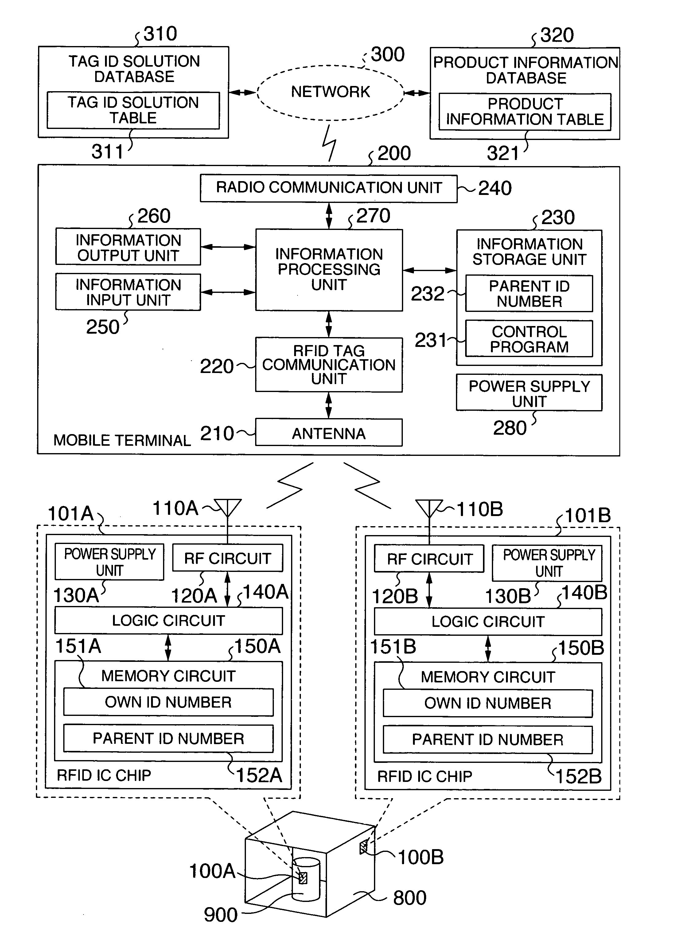
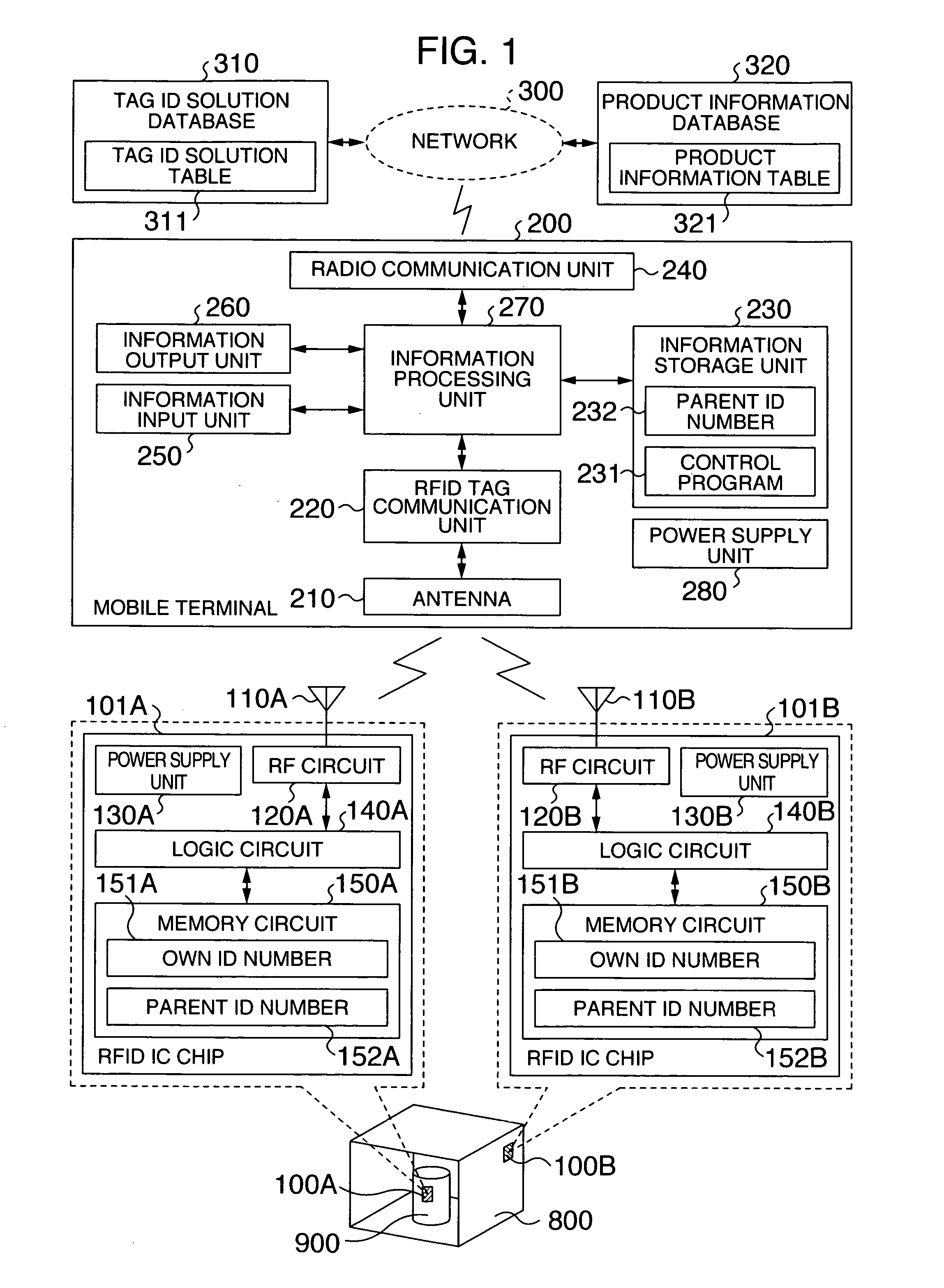
[0024] To begin with, a first embodiment will be described. FIG. 1 is a block diagram illustrating components of an RFID tag system according to the first embodiment. In FIG. 1, the RFID tag system comprises RFID tags 100A, 100B, a mobile terminal 200, a network 300, a tag ID solution database 310, and a product information database 320. Each of the RFID tags 100A, 100B has a function of reading and writing a tag ID stored therein using radio communications, and is attached to an associated product.

[0025] In FIG. 1, the RFID tag 100A is attached to a product 900, while the RFID tag 100B is attached to a container 800. The container 800 represents a bock, a shelf or the like which can accommodate the product 900. Alternatively, the container 800 may not be a physical entity but may represent a logical set that has the product 900 as an element, such as a group...


PUM


Abstract

A hierarchical structure is established among a plurality of RFID tags, such that ID numbers can be read only from RFID tags which belong to a particular layer. RFID tag can control whether permission should be given to read its ID number therefrom to protect the ID number. Data held in the RFID tag can be read from the outside. RFID tag comprises a memory circuit having a function of holding data, and a logic circuit having a function of processing a control command received from outside. Memory circuit stores an own ID nmber for identifying the RFID tag itself, and a parent ID number for identifying a second RFID tag. When RFID tag receives an ID number read command which contains first data as a parameter from outside, the logic circuit outputs the own ID number to outside only when the first data matches the parent ID number.

Description

INCORPORATION BY REFERENCE [0001] The present application claims priority from Japanese application JP2004-378762 filed on Dec. 28, 2004, the content of which is hereby incorporated by reference into this application. BACKGROUND OF THE INVENTION [0002] The present invention relates to a radio frequency identification (RFID) tag which comprises an radio communication IC chip, and an information system using the RFID tag. [0003] In recent years, the RFID tag has drawn attention as a technology for identifying a variety of “objects”. The RFID tag is a module comprised of a very small radio communication IC chip and an antenna, and can be designed in a variety of shapes such as a card shape, a label shape and the like. The radio communication IC tip of the RFID tag has a built-in memory from which data can be read in a non-contact manner using a dedicated reader (hereinafter called the “tag reader”). There is also an RFID tag which can write data into a built-in memory in a non-contact ...

Claims


Application Information

Patent Timeline
IPC IPC(8): H04Q5/22
CPCG06K7/0008G06K19/0723G06K2017/0051G06Q20/203
Inventor AIKAWA, MAKOTOTAKAMI, YUTAKAFUKUSHIMA, SHINICHIROMORITANI, MASUMIKAZUNORI, HASHIMOTO
Owner HITACHI LTD
Why Eureka
Try Eureka