Direct backlight module for flat panel monitor

a flat panel monitor and backlight module technology, applied in lighting and heating equipment, lighting device details, instruments, etc., can solve the problems of inability to reduce the thickness of the lcd panel and provide the lcd panel with a uniform brightness, and achieve the effect of thin flat panel monitors and simple and quick installation procedures

Inactive Publication Date: 2006-07-06
WENG ALLEN
View PDF13 Cites 2 Cited by
  • Summary
  • Abstract
  • Description
  • Claims
  • Application Information

AI Technical Summary

Benefits of technology

[0004] The present invention provides a direct backlight module for a flat panel monitor. The light source of the direct backlight module is an illuminating layer so that the present invention doesn't only provide simple and quick installation procedures, but also produces a much thinner flat panel monitor.

Problems solved by technology

Nonetheless, most of these inventions adopt a pipe type light bulb as their light sources, and therefore are unable to reduce their thickness and provide the LCD panel with a uniform brightness.

Method used


Image

  • Direct backlight module for flat panel monitor
  • Direct backlight module for flat panel monitor
  • Direct backlight module for flat panel monitor

Examples


first embodiment

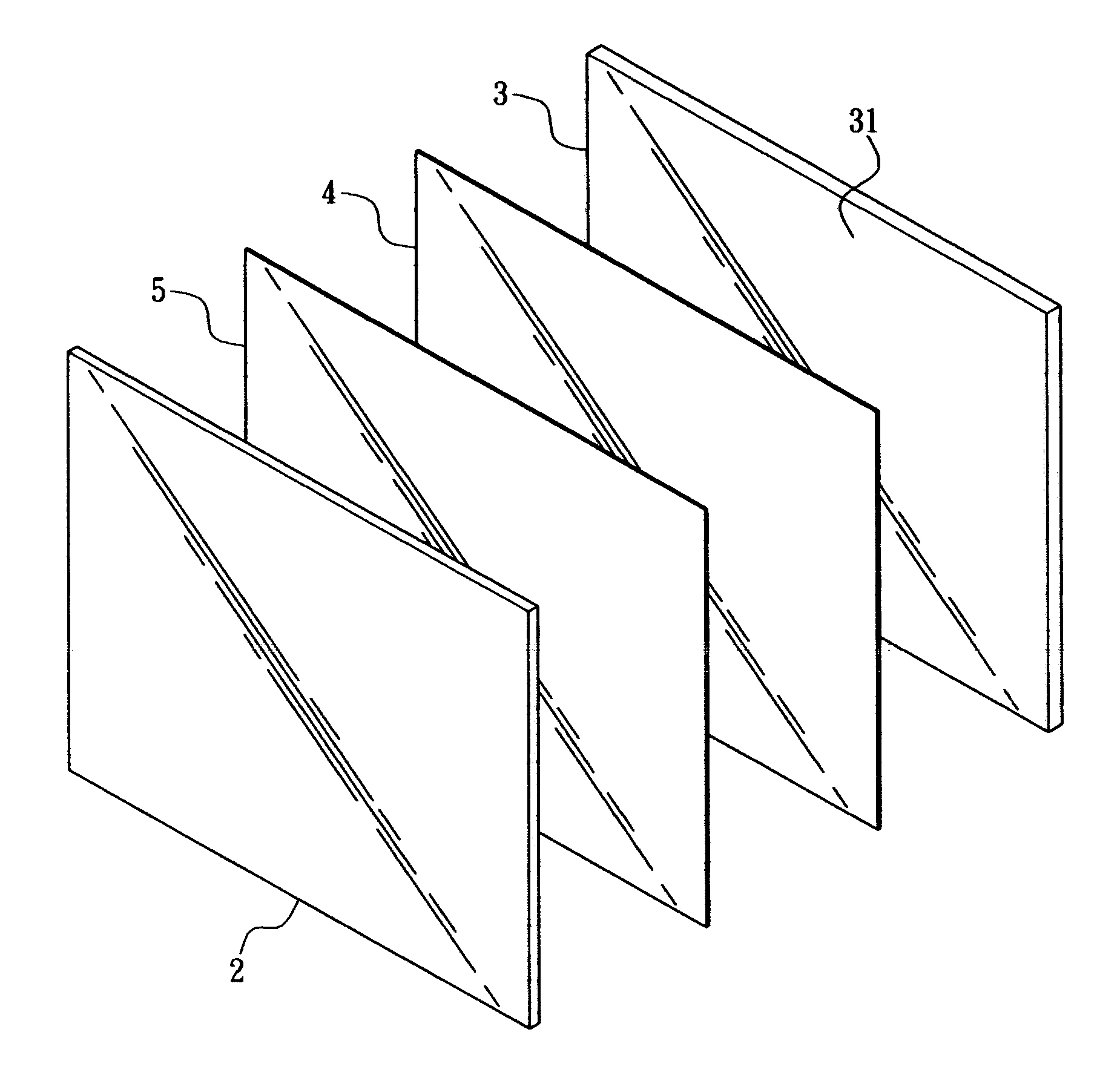
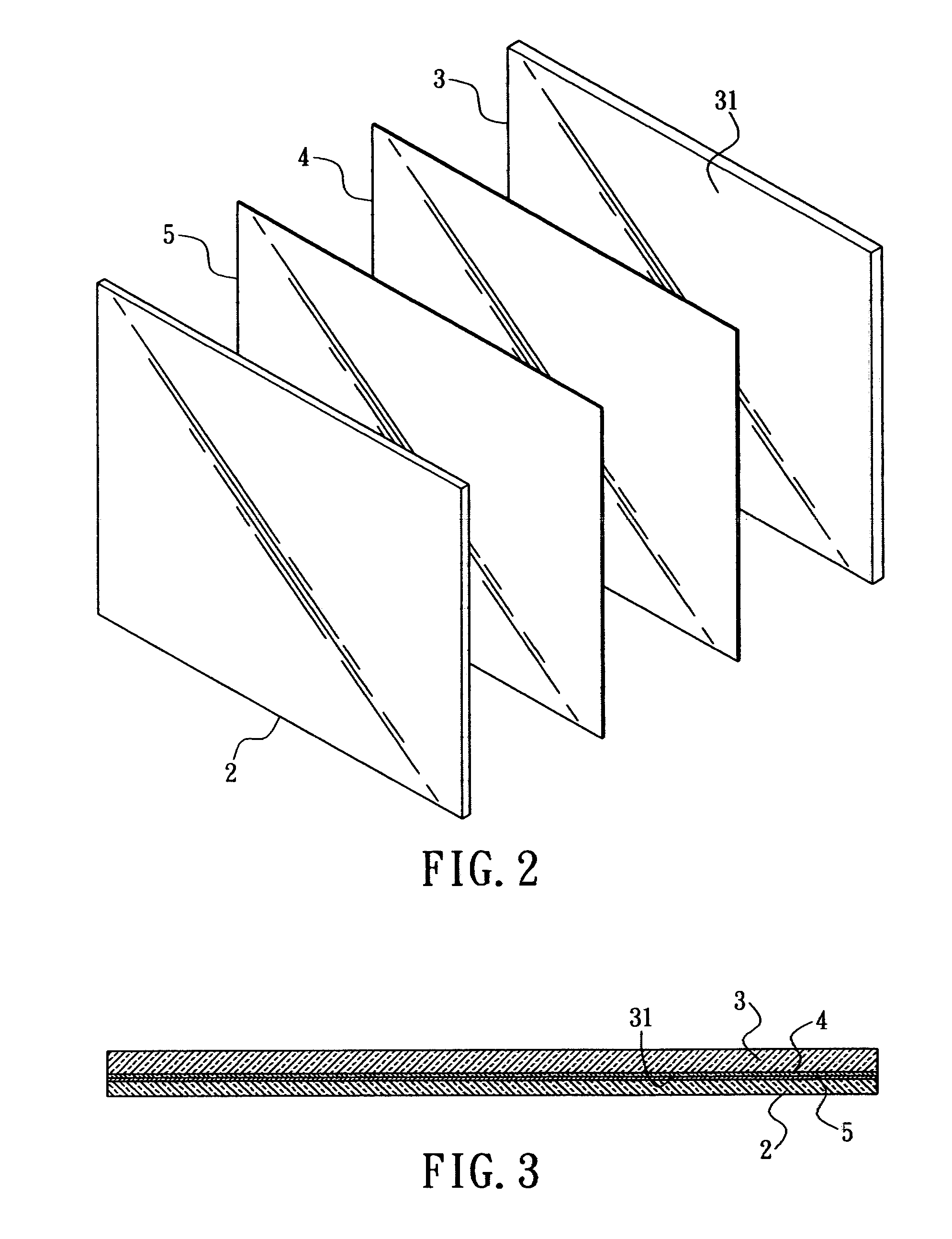
[0020] Referring to FIGS. 2 and 3, a direct backlight module for a flat panel monitor of the present invention is illustrated. The direct backlight module, which is applied to illumination of a LCD panel 2, includes a first plate 3, an opposite second plate 5, and an illuminating layer 4 that is sandwiched between the first plate 3 and the second plate 5.

[0021] The first plate 3 is a planar plate, and is a back plate of the present backlight module. It is a base onto which the illuminating layer 4 and the second plate 5 are assembled. The first plate 3 provides a receptive space 31 for receiving the illuminating layer 4. In the present embodiment, the first plate 3 is a reflector, and the space before the front of the first plate 3 defines the receptive space 31.

[0022] The illuminating layer 4 is installed inside the receptive space 31 of the first plate 3, sandwiched between the first plate 3 and the second plate 5. The illuminating layer 4 is a planar light source, which provides...

fourth embodiment

[0026] Referring to FIGS. 6 through 8, the third and a direct backlight module for a flat panel monitor of the present invention are illustrated. Similar to foresaid embodiments, the direct backlight module includes a first plate 3, an opposite second plate 5, and an illuminating layer 4. The first plate 3 has a flat hollow inner space with an opening 32. The opening 32 may be cut from any edge of the first plate 3, top or bottom or left or right edge. The hollow inner space defines the receptive space 31 into which the illumination layer 4 is installed via the opening 32. The first plate 3 with an illumination layer 4 installed therein is further combined with the second plate 5 that is preferably a diffuser plate.

[0027] Referring to FIGS. 9 and 10, the fifth embodiment of a direct backlight module for a flat panel monitor of the present invention is illustrated. Unlike aforementioned embodiments, the illumination layer 4 of the fifth embodiment utilizes a plurality of LEDs as its ...


PUM


Abstract

A direct backlight module for a flat panel monitor includes a first plate, an opposite second plate, and an illuminating layer that is sandwiched between the first plate and the second plate. The first plate is preferably a reflector. The second plate is preferably a diffuser. The illumination layer may be a single layer cold light plate, or a multi-layer cold light plate, or a LED plate that comprises a planar substrate, a plurality of LED bare chips, and a BEF sheet. The LED bare chips are mounted on one surface of the planar substrate, and the BEF sheet is then secured onto the planar substrate, thereby encapsulating the LED bare chips between the planar substrate and the BEF sheet.

Description

BACKGROUND OF THE INVENTION [0001] The present invention relates in general to a direct backlight module for a flat panel monitor, and more specifically, to a backlight module whose light source is an illuminating layer. [0002] Depending on the arrangement of their light sources, conventional backlight modules can be divided into two major groups, edge lighting and direct lighting. A typical direct backlight module is illustrated in FIG. 1. The direct backlight module includes a box body 1; a concaved light guide plate 10 within which a hollow chamber 11 is formed; at least one light source 12 installed inside the hollow chamber 11, which can be a PL bulb, a cold cathode fluorescent lamp, and the like; a multi-layer brightness enhancement film (BEF) 13 disposed at the light exit surface of the box body 1; and a diffuser 14. The backlight module is further aligned parallel and combined with a liquid crystal display (LCD) panel 15. The conventional direct backlight module is relativel...

Claims


Application Information

Patent Timeline
Patent Type & Authority Applications(United States)
IPC IPC(8): F21V5/00F21V7/04
CPCG02F1/133602
Inventor WENG, ALLEN
Owner WENG ALLEN
Why Eureka
Try Eureka