Vehicular lamp
a technology for lamps and lampshades, applied in lighting applications, lighting and heating apparatus, instruments, etc., can solve the problems of poor illumination visibility of lamps, and achieve the effect of excellent visibility and good overall unlit appearan
- Summary
- Abstract
- Description
- Claims
- Application Information
AI Technical Summary
Benefits of technology
Problems solved by technology
Method used
Image

Examples
second embodiment
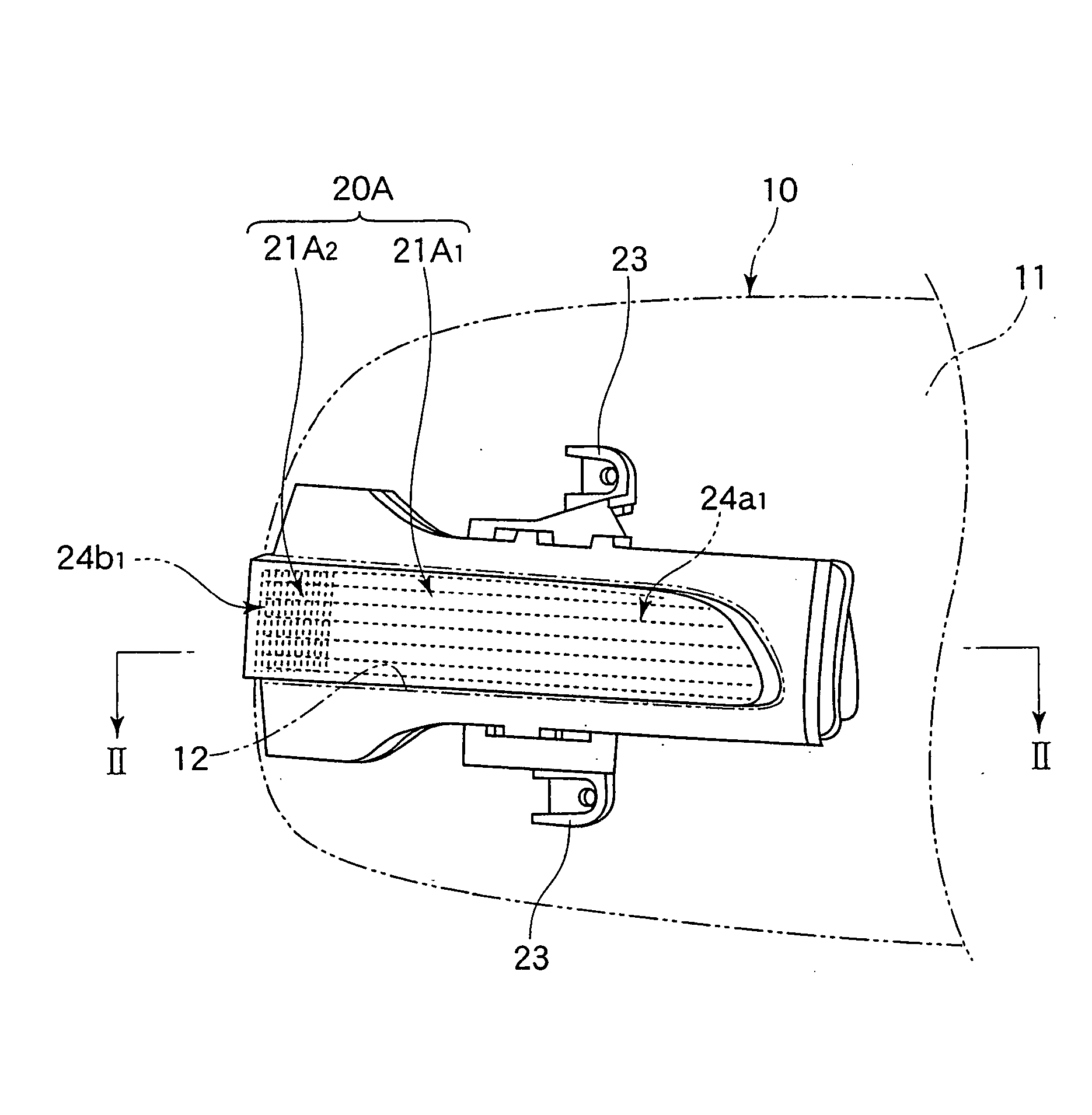
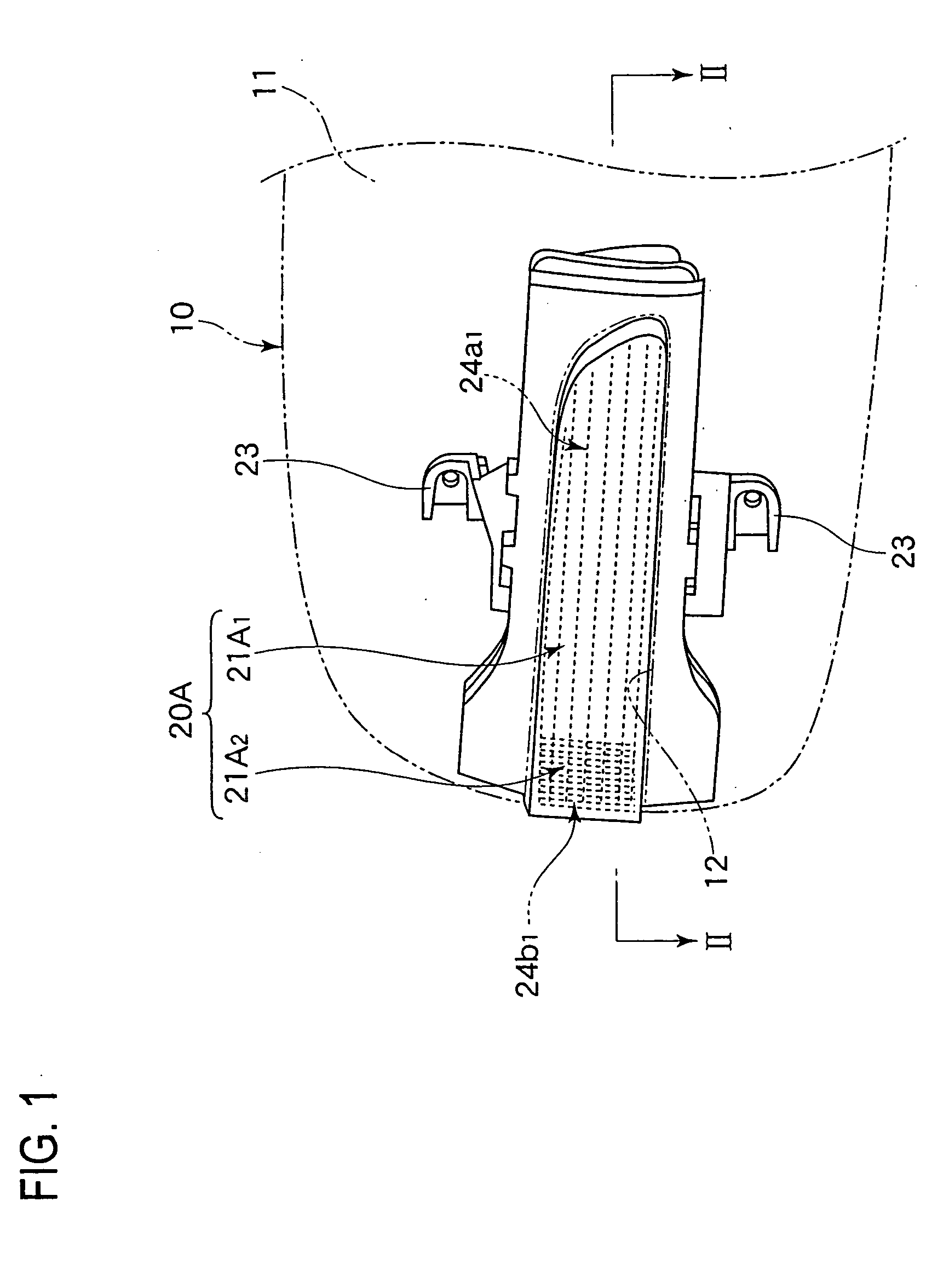
[0056]FIG. 3 shows, in cross-section, a marker lamp according to the present invention.
[0057] In the first embodiment described above, the entire front lens 24 is transparent. However, in the second embodiment, the front lens 24B of the multi-functional lamp 20B is a two-color lens comprised of a transparent portion 24B1 making a daytime running lamp 24B1 and an amber-colored portion 24B2 making a side turn signal lamp 21B2. Accordingly, it is possible to use LED's that emit white light for the LED 26 serving as the light source for the daytime running lamp 21B1 and for the LED 29B serving as the light source for the side turn signal lamp 21B2.
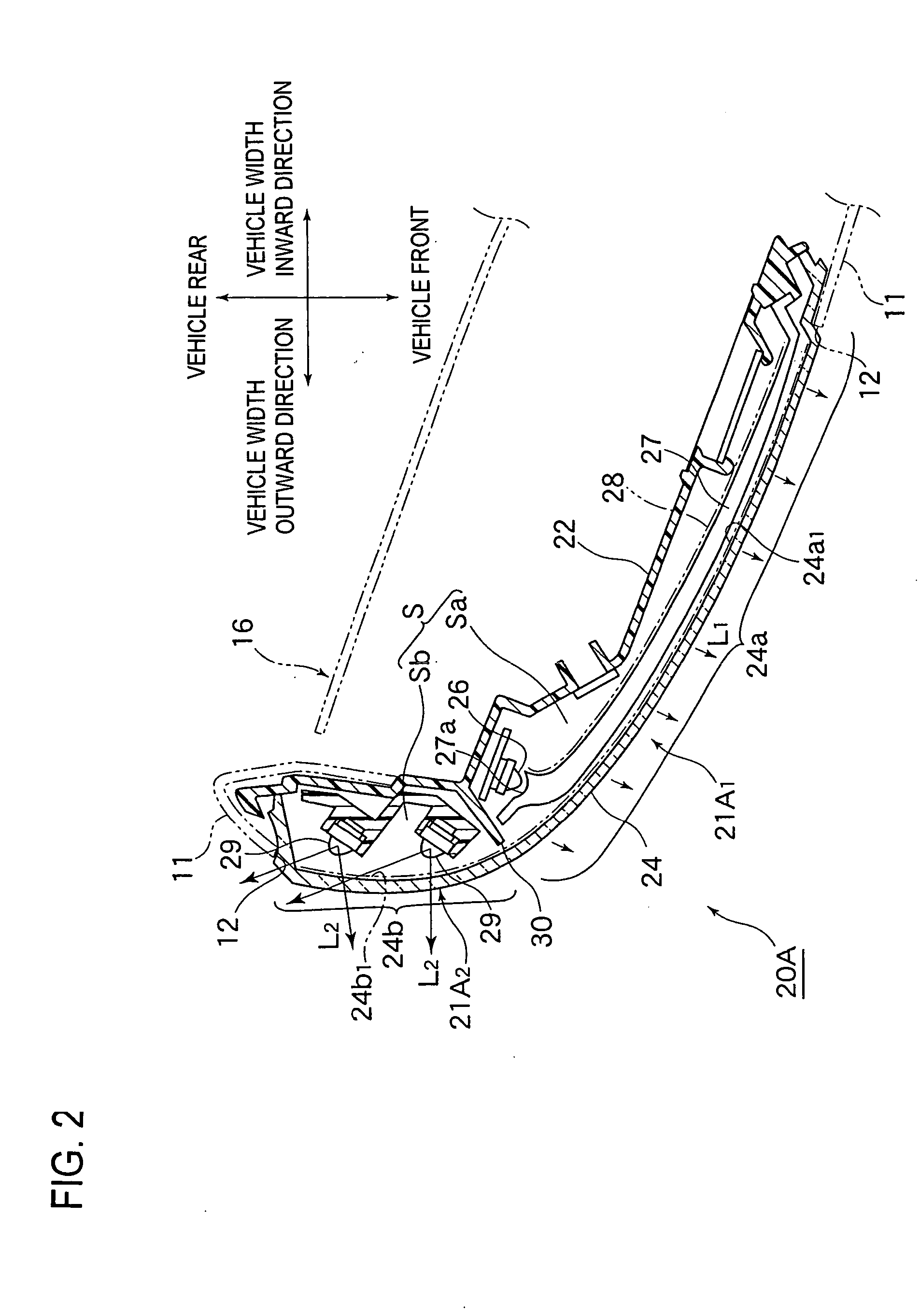
[0058] In the first embodiment, as seen from FIG. 2, the partition 30 is formed on the lamp body 22. In the multi-functional lamp 20B of the second embodiment shown in FIG. 3, the front lens 24B is formed with a partition 30B (at a portion of the front lens 24B combining the transparent portion 24B1and the amber-colored portion 24B2), so that...
first embodiment
[0059] The partition 30B located between the light emission areas 24a and 24b of the front lens 24B defines a vertical groove 32 that has a predetermined width and extends in the vertical direction. The housing outer wall 11 (or the outer wall 11 of the mirror housing 10) is formed with openings 12a and 12b so as to positionally correspond, respectively, to the light emission areas 24a and 24b of the front lens 24B. The openings 12a and 12b are separated by a vertical rib 13 that extends in the vertical direction (in other words, the opening 12 shown in the first embodiment is separated into the laterally adjacent first and second openings 12a and 12b by the vertical rib 13). The width of the vertical rib 13 conforms to the width of the vertical groove 32.
[0060] Accordingly, when the multi-functional lamp 20B is installed in the housing outer wall 11, the entirety of the light emission areas 24a and 24b of the front lens 24b are respectively fitted in the openings 12a and 12b so tha...
third embodiment
[0064]FIG. 4 shows, in cross-section, a marker lamp according the present invention.
[0065] In the first and second embodiments, the present invention is described with reference to an integrated side turn signal lamp / daytime running lamp in which a daytime running lamp and a side turn signal lamp are integrated. In the third embodiment, the present invention is applied to a daytime running lamp 20C.
[0066] In this daytime running lamp 20C, a light guide inner lens 27C is disposed in the lamp chamber space S defined by the lamp body 22 and the front lens 24. The light guide inner lens 27C extends up to the position of an end portion on the side of the lamp chamber space S that wraps around toward the vehicle backward direction.
[0067] Inside the lamp chamber space S, an LED 26 that emits white light is disposed to face the vehicle forward direction and also to face the incident light end portion 27a of the light guide inner lens 27C. An LED 29B that emits white light is disposed to f...
PUM
 Abstract
Description
Claims
Application Information
 - R&D
- Intellectual Property
- Life Sciences
- Materials
- Tech Scout
- Unparalleled Data Quality
- Higher Quality Content
- 60% Fewer Hallucinations
Browse by: Latest US Patents, China's latest patents, Technical Efficacy Thesaurus, Application Domain, Technology Topic, Popular Technical Reports.
© 2025 PatSnap. All rights reserved.Legal|Privacy policy|Modern Slavery Act Transparency Statement|Sitemap|About US| Contact US: help@patsnap.com