
Memory cell having improved read stability

Active Publication Date: 2006-07-06
MICROSOFT TECH LICENSING LLC
View PDF5 Cites 129 Cited by
  • Summary
  • Abstract
  • Description
  • Claims
  • Application Information

AI Technical Summary

Benefits of technology

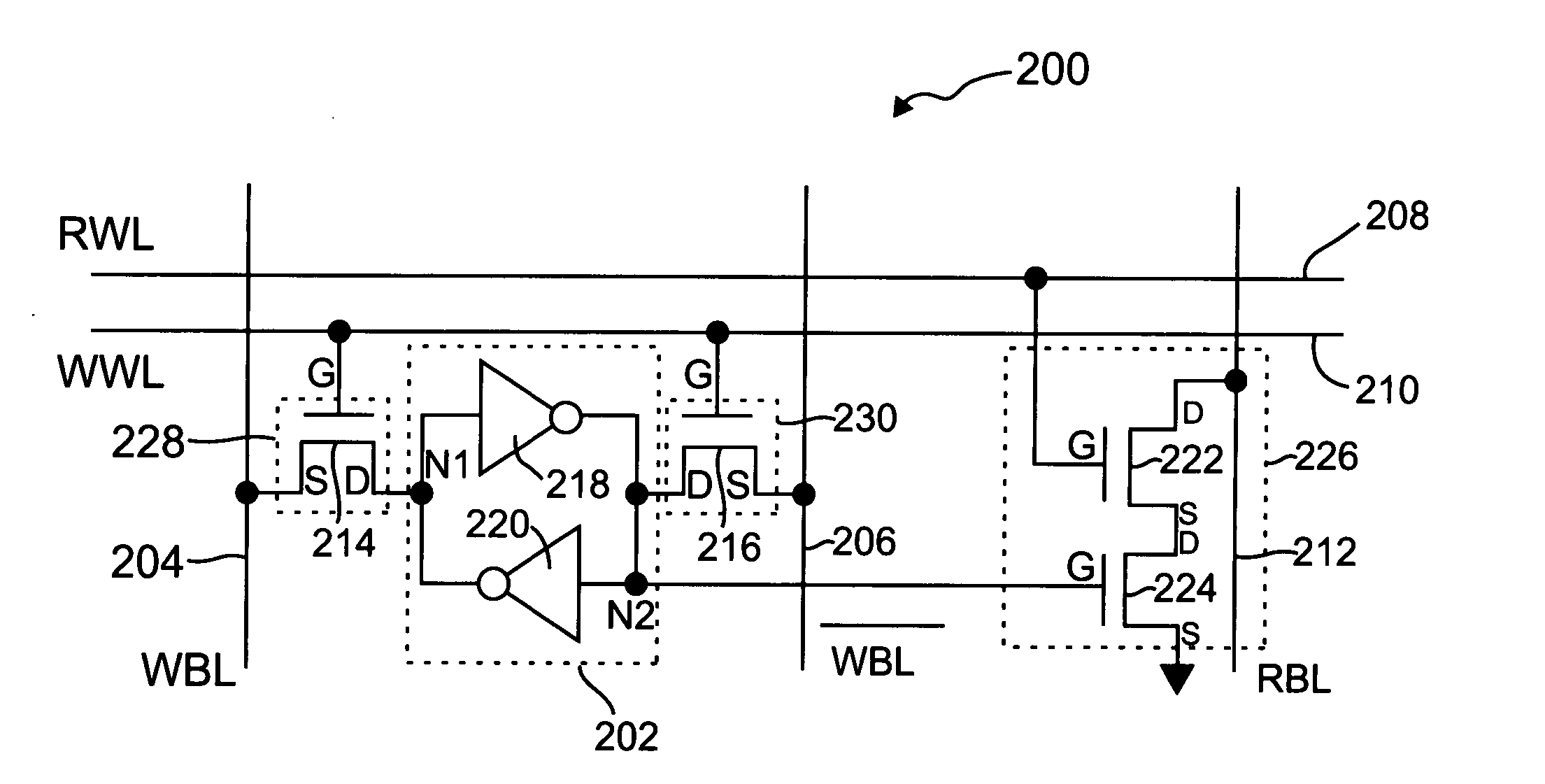
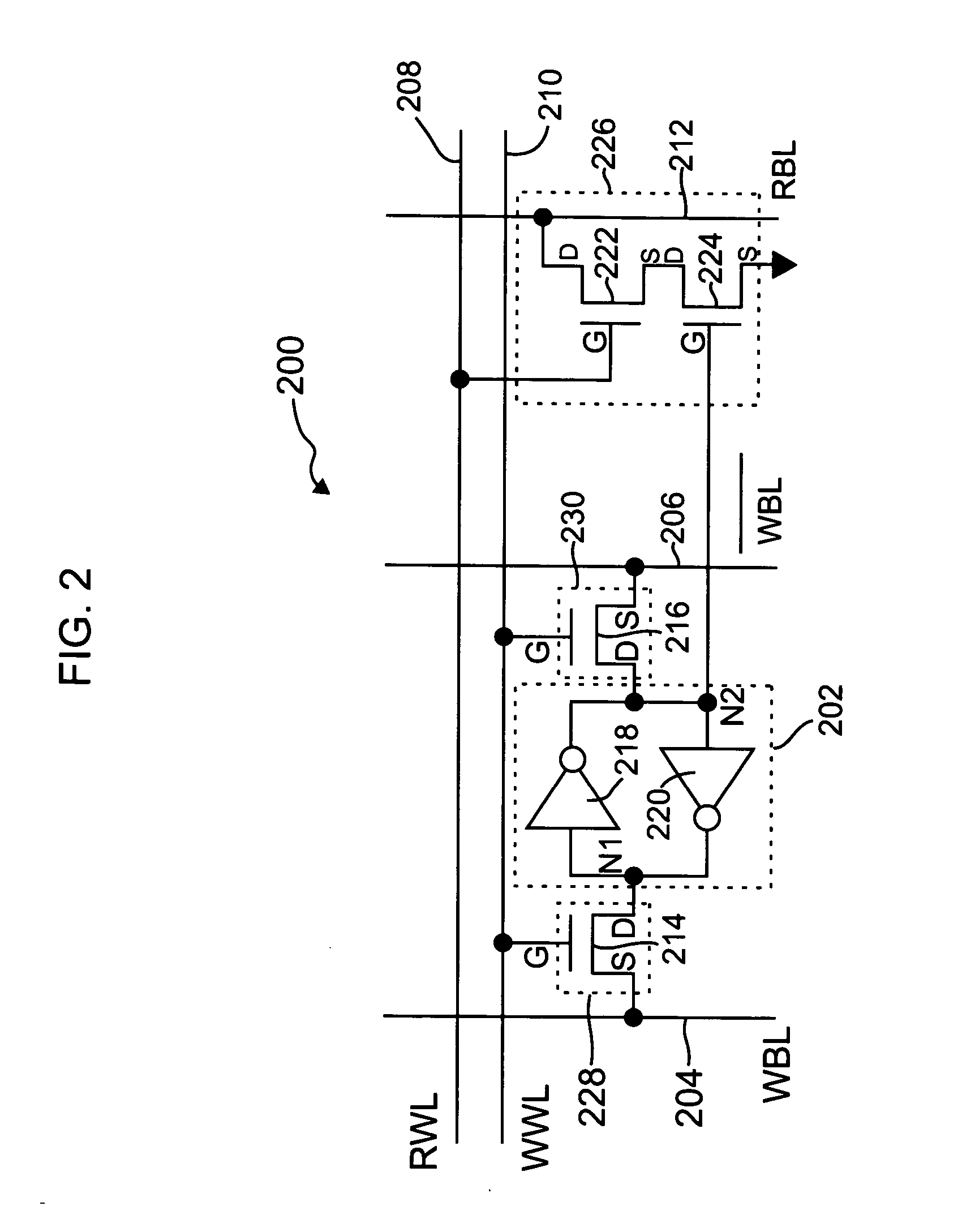
[0007] In accordance with the aforementioned need, the present invention, in an illustrative embodiment, is an improved memory cell architecture that virtually eliminates disturbs of the memory cell during a read operation by altering a read mechanism of the memory cell. The improved memory cell is configured such that a storage element comprised in the cell is essentially electrically isolated from a corresponding word line or bit line during the read operation. The memory cell architecture of the invention is well-suited for use in an SRAM array.

Problems solved by technology

While this memory cell arrangement offers a compact structure, the 6-T memory cell has many disadvantages, particularly its potential inability to scale with overall technology advancements due, at least in part, to stability problems which are often exacerbated as integrated circuit process dimensions shrink.
Stability problems generally arise whenever stored voltages on internal nodes of the memory cell are disturbed.
This threshold voltage scatter effect essentially magnifies the disturb voltage in 6-T memory cells, which can lead to stability failures in the SRAM array in which the 6-T memory cells are employed.
The scaling of power supply voltages further degrades stability by reducing noise margins in the memory cell.
These techniques, however, generally involve a significant tradeoff between memory cell stability and performance, and may not be sufficient for future process technologies.

Method used


Image

  • Memory cell having improved read stability
  • Memory cell having improved read stability
  • Memory cell having improved read stability

Examples


Embodiment Construction

[0021] The present invention will be described herein in the context of an illustrative static memory cell suitable for use, for example, in an SRAM array. It should be appreciated, however, that the invention is not limited to this or any particular memory cell architecture. Rather, the invention is more generally applicable to techniques for advantageously eliminating disturbs in a memory cell, thereby improving a stability of the memory cell, during a read operation. The memory cell of the present invention may be easily fabricated using standard integrated circuit (IC) process technology, such as, for example, a complementary metal-oxide-semiconductor (CMOS) fabrication process. Consequently, the cost of manufacturing the memory cell is not significantly increased compared to standard static memory cells.

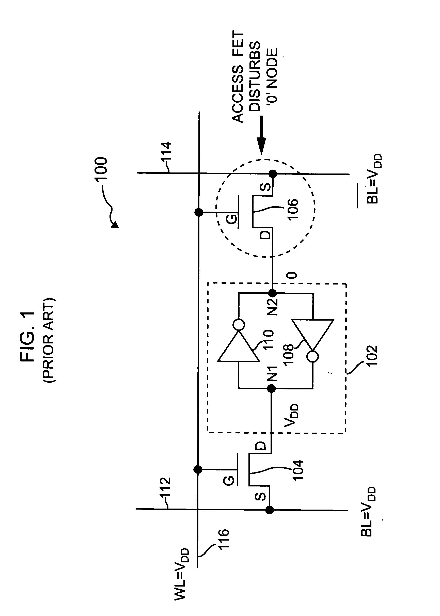
[0022]FIG. 1 is a schematic diagram illustrating a standard 6-T memory cell 100. The memory cell 100 includes a static storage element 102 that is selectively connectable to bi...


PUM


Abstract

A memory cell for use in a memory array includes a storage element for storing a logical state of the memory cell, a write circuit and a read circuit. The write circuit is operative to selectively connect a first node of the storage element to at least a first write bit line in the memory array in response to a write signal for selectively writing the logical state of the memory cell. The read circuit includes a substantially high impedance input node connected to the storage element and an output node connectable to a read bit line of the memory array. The read circuit is configured to generate an output signal at the output node which is representative of the logical state of the storage element in response to a read signal applied to the read circuit. The memory cell is configured such that the write circuit is disabled during a read operation of the memory cell so as to substantially isolate the storage element from the first write bit line during the read operation. A strength of at least one transistor device in the storage element is separately optimized relative to a strength of at least one transistor device in the write circuit and / or the read circuit.

Description

CROSS-REFERENCE TO RELATED APPLICATION [0001] This application claims the benefit of priority to U.S. Provisional Application No. 60 / 640,587 filed on Dec. 30, 2004, the disclosure of which is incorporated by reference herein.FIELD OF THE INVENTION [0002] The present invention relates generally to memory devices, and more particularly relates to a static memory cell architecture having improved stability during a read operation. BACKGROUND OF THE INVENTION [0003] As integrated circuit technologies are scaled, stability in a static memory cell becomes a major concern affecting the design of reliable memory arrays, including, for example, static random access memory (SRAM) arrays. Most static memory cells employ a conventional six-transistor (6-T) architecture, as depicted in FIG. 1. While this memory cell arrangement offers a compact structure, the 6-T memory cell has many disadvantages, particularly its potential inability to scale with overall technology advancements due, at least i...

Claims


Application Information

Patent Timeline
IPC IPC(8): G11C8/00
CPCG11C11/413H01L27/11H01L27/1104H10B10/00H10B10/12
Inventor CHANG, LELANDDENNARD, ROBERT H.MONTOYE, ROBERT KEVIN
Owner MICROSOFT TECH LICENSING LLC
Learn More