
Using temporal and spatial coherence to accelerate maximum/minimum intensity projection

a temporal and spatial coherence technology, applied in the field of volume rendering, can solve the problem of intrinsically expensive ray casting based mip

Active Publication Date: 2006-07-06
SIEMENS MEDICAL SOLUTIONS USA INC
View PDF5 Cites 15 Cited by
  • Summary
  • Abstract
  • Description
  • Claims
  • Application Information

AI Technical Summary

Benefits of technology

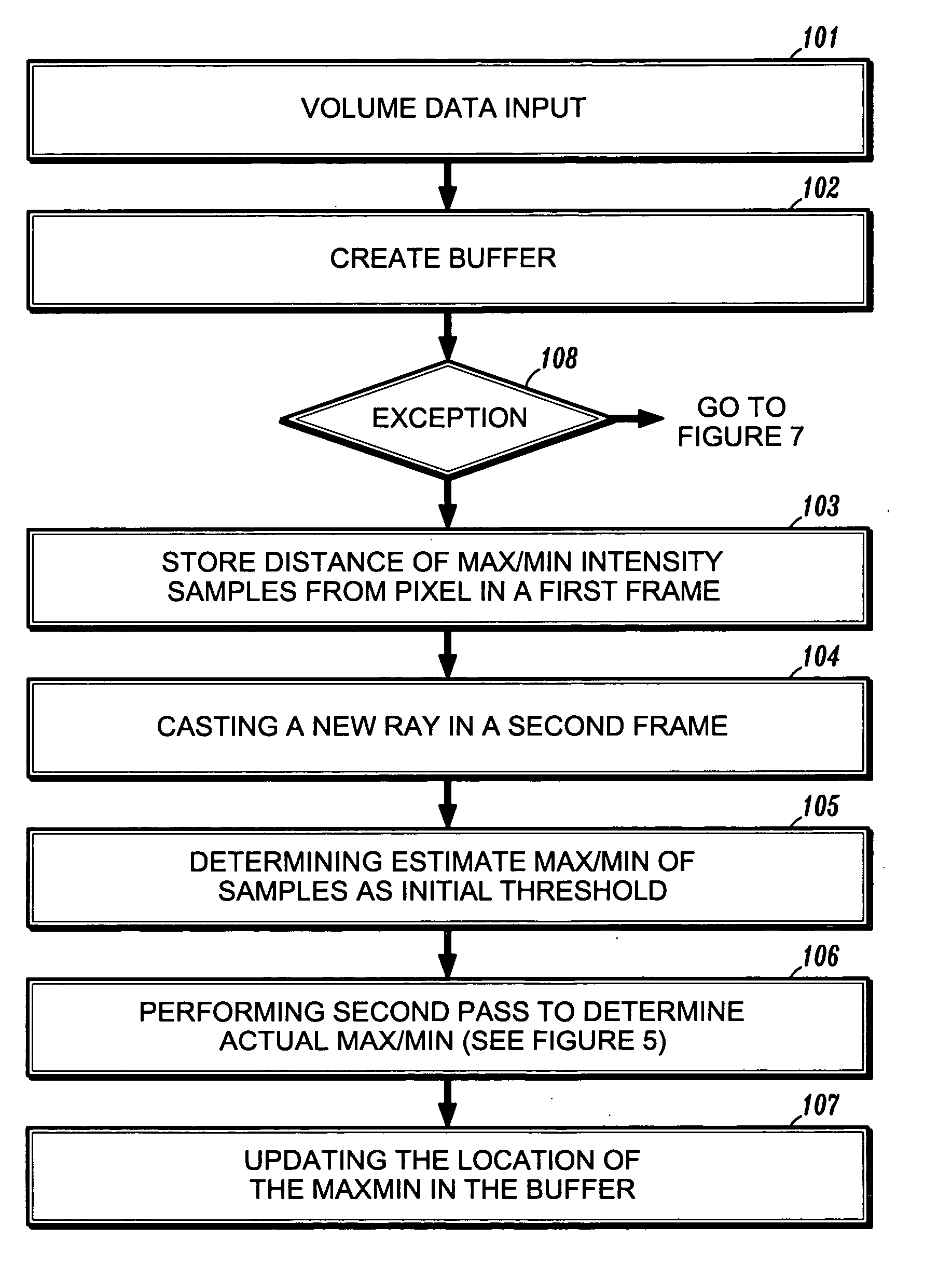
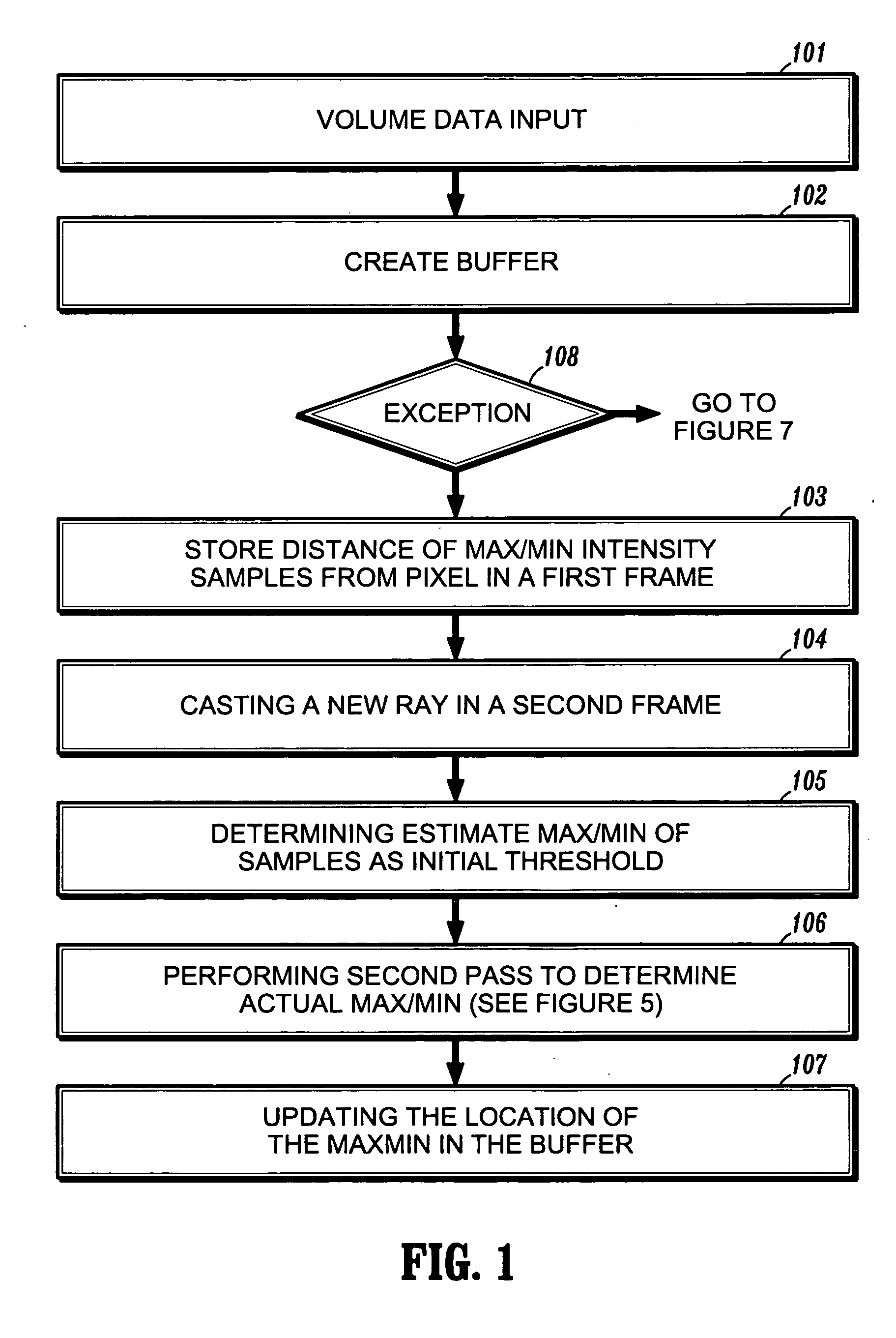
[0012] According to an embodiment of the present disclosure, a `computer implemented method casting a ray through an image includes providing a reduced path octree structure of a volumetric image, said reduced path octree comprising a plurality of first level nodes, wherein each first level node contains a plurality of intensities, wherein each node includes a minimum intensity value and a maximum intensity value, defining a position determined as a maximum / minimum along a neighboring ray as an estimated threshold for a current frame, and visitng each first level node along the ray, wherein a maximum / minimum intensity value for the first level nodes is selected by the threshold, sampling each intensity within each first level node, and saving a maximum / minimum value of each said sample.

Problems solved by technology

Ray casting based MIP is intrinsically expensive since the rays must go through and tri-linearly interpolate all the samples along them to find the maximal values.

Method used


Image

  • Using temporal and spatial coherence to accelerate maximum/minimum intensity projection
  • Using temporal and spatial coherence to accelerate maximum/minimum intensity projection
  • Using temporal and spatial coherence to accelerate maximum/minimum intensity projection

Examples


Embodiment Construction

[0022] By reversing the maximum and minimum, methods presented herein are mirror symmetric. Therefore, methods described for MIP can also be applied to MinIP. For simplicity, only methods for determining MIP are described in detail.

[0023] According to an embodiment of the present disclosure, a searching method utilizes coherence information. The coherence information can be obtained in a neighboring ray (spatial coherence) or in a previous frame (temporal coherence) to obtain an initial threshold. The threshold can further accelerate a MIP method.

[0024] To reduce MIP overhead and obtain a threshold, both the temporal coherence and the spatial coherence are used to estimate the initial threshold.

[0025] The location and the value of the maximum intensity along a ray typically does not change much from frame to frame as long as a change in the viewing angle is small, e.g., about 5 degrees. According to an embodiment of the present disclosure, a method for determining a MIP threshold...


PUM


Abstract

A computer-implemented method for intensity projection includes providing volume data, determining an estimated threshold for determining a maximum / minimum intensity value in the volume data from temporal coherence and spatial coherence information, performing the second pass for determining an actual maximum / minimum value along the new ray, wherein the second pass uses the estimated threshold as an initial threshold, and updating the buffer with a new location value where the actual maximum / minimum value for the next frame was determined.

Description

[0001] This application claims priority to U.S. Provisional Application Ser. No. 60 / 638,230, filed on Dec. 22, 2004, which is herein incorporated by reference in its entirety.BACKGROUND OF THE INVENTION [0002] 1. Technical Field [0003] The present invention relates to volume rendering, and more particularly to a system and method for maximum / minimum intensity projection. [0004] 2. Discussion of Related Art [0005] Maximum Intensity Projection (MIP) is a widely accepted volume rendering technique that is used to extract high-intensity structure from volumetric scalar data. At each pixel the highest sample value encountered along the corresponding viewing ray is determined. MIP is commonly used to extract vascular structure from medical CT or MRI data sets, for example, angiography. MIP exploits the fact, that within angiography data sets the data values of vascular structures are higher than the values of the surrounding tissue. By depicting the maximum data value seen through each pi...

Claims


Application Information

Patent Timeline
Patent Type & Authority Applications(United States)
IPC IPC(8): G06K9/00
CPCG06T15/08
Inventor YANG, LININGXIE, MIN
Owner SIEMENS MEDICAL SOLUTIONS USA INC
Learn More