Shallow water watercraft lift

a technology for watercraft and shallow water, applied in special-purpose vessels, floating buildings, transportation and packaging, etc., can solve the problems of not sufficiently addressing problems, watercraft may be subject, and existing watercraft lifts,

Inactive Publication Date: 2006-07-06
SUNSTREAM CORP
View PDF17 Cites 7 Cited by
  • Summary
  • Abstract
  • Description
  • Claims
  • Application Information

AI Technical Summary

Benefits of technology

[0015] Yet another aspect of the invention is a method of converting an existing watercraft lift usable to lift a watercraft in water of a first minimum depth to a modified watercraft lift usable to lift the watercraft in water of a second minimum depth less than the first minimum depth, where the watercraft has a first watercraft elevational position when floating in the water prior to engagement with the lift and where the watercraft lift being converted has a translating watercraft support sized to support the watercraft thereon and movable between a lowered translating support position and a raised translating support position. The method includes providing at least one watercraft initial lift; and attaching the watercraft initial lift to the existing watercraft lift in position to be engaged by and lift the watercraft to a second watercraft elevational position higher than the first watercraft elevational position as the watercraft is moved into engagement therewith and over the translating watercraft support for engagement thereby for lifting of the watercraft off of the watercraft initial lift as the translating watercraft support is moved upward from the lowered translating bunk position to the raised translating bunk position whereat the watercraft is in a third watercraft elevational position higher than the second watercraft elevational position. In this method of converting, the watercraft initial lift may include first and second watercraft initial lift members, and attaching the watercraft initial lift may include attaching the first watercraft initial lift member in a position to first engage and lift the watercraft upon the watercraft first being moved onto the lift, and attaching the second watercraft lift member in a position spaced apart from the first watercraft initial lift member to engage the watercraft after the watercraft is first engaged by the first watercraft initial lift member, with the first and second watercraft initial lift members being arranged to support the watercraft positioned thereon at the second watercraft elevational position without requiring securing of the watercraft to the lift.

Problems solved by technology

A watercraft may be subject to several difficulties if moored within the water: damage to the watercraft may occur when wave action or other in-water forces cause the hull of the watercraft to strike adjacent in-water structures such as docks or seawalls; damage may also result from longer term effects such as vegetative buildup on the hull of the watercraft.
Existing watercraft lifts, however, do not sufficiently address problems caused by fluctuating water levels and / or consistently shallow waters.
Lifts with translating bunks provide adequate range, but do not function in extreme shallow water.
Existing translating bunk watercraft lifts may become functionally useless when water levels drop below a certain point.
This occurs when the watercraft support platform, typically consisting of supporting bunks, is sufficiently high in the lowered position relative to the watercraft and waterline that friction forces between the watercraft and support platform cause watercraft ingress or egress to become impossible or unsafe.
Generally, watercraft lifts do not employ specific features that allow the lifts to operate in extreme shallow water.
Since lifts are typically used along the shoreline, water depth has limited use of free-standing lifts for many locations.
These watercraft lifts, however, are generally not as desirable due to limitations in lifting range, and that they require means to keep the boat from rolling off the bunks.
This device, however, is limited in that the watercraft can be loaded on the lift smoothly, since the rollers need to be positioned high enough to lift the hull out of the water.
The geometry lifts the front of the boat to approximately 30 degrees, which is widely considered to be undesirable to the user.
This device is limited, since it requires a person connect the winch to the front of the boat, and winch the boat on the lift.
This typically requires the user to disembark from the boat, which is undesirable.
Similarly, the lifting height range of this device is limited, so the watercraft may remain subject to damage from moderate wave action or other perils meant to be avoided by the use of a watercraft lift.
This invention also fails to address watercraft protection issues in that the aft portion of the watercraft is not significantly lifted from the water and may remain subject to damage from wave action as a result.
Not lifting the rear of the boat from the water is undesirable, since most boat engines are in the rear.
Again, relatively steep slope angles may cause additional operator difficulties when attempting to use the watercraft.

Method used


Image

  • Shallow water watercraft lift
  • Shallow water watercraft lift
  • Shallow water watercraft lift

Examples


Embodiment Construction

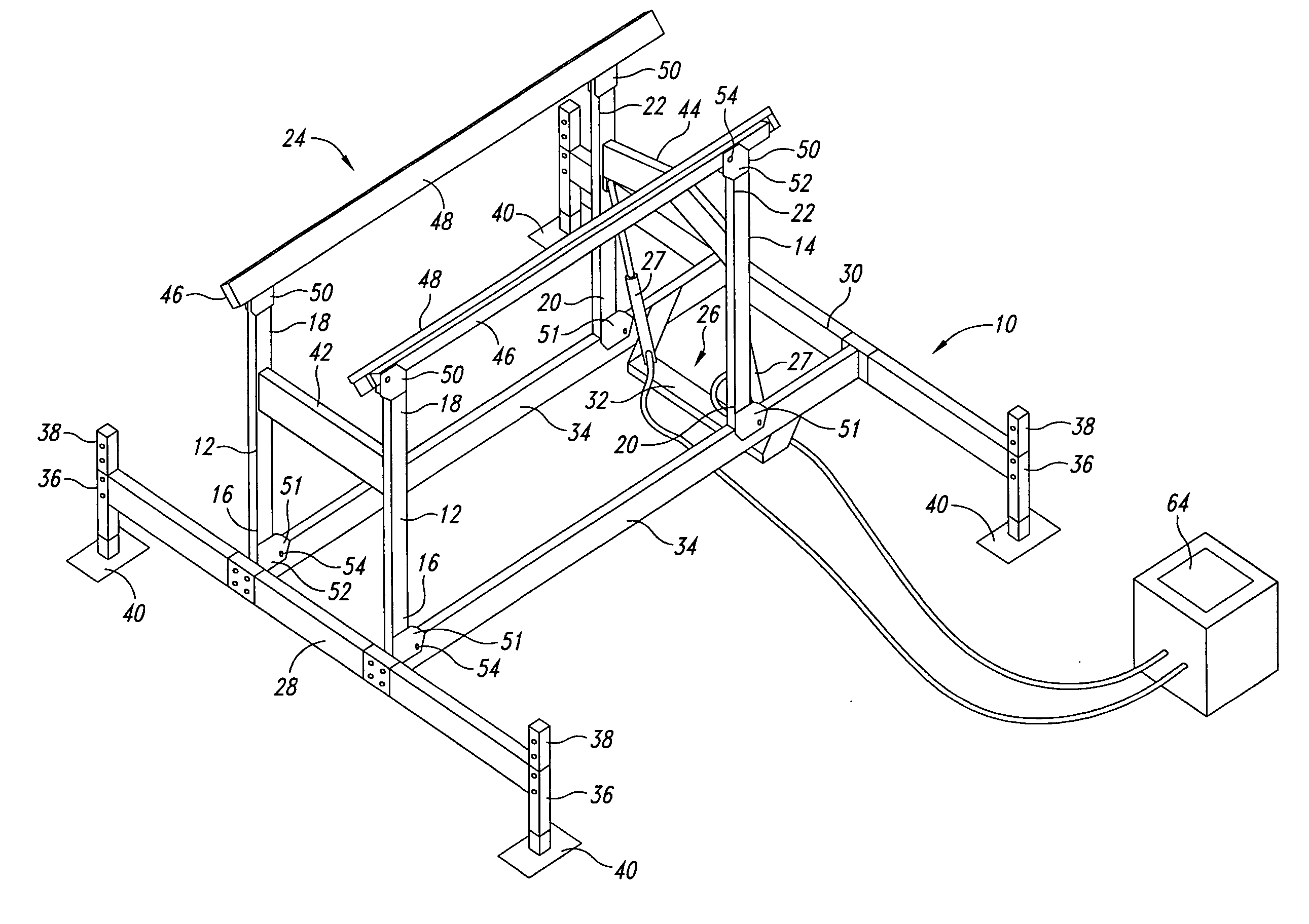
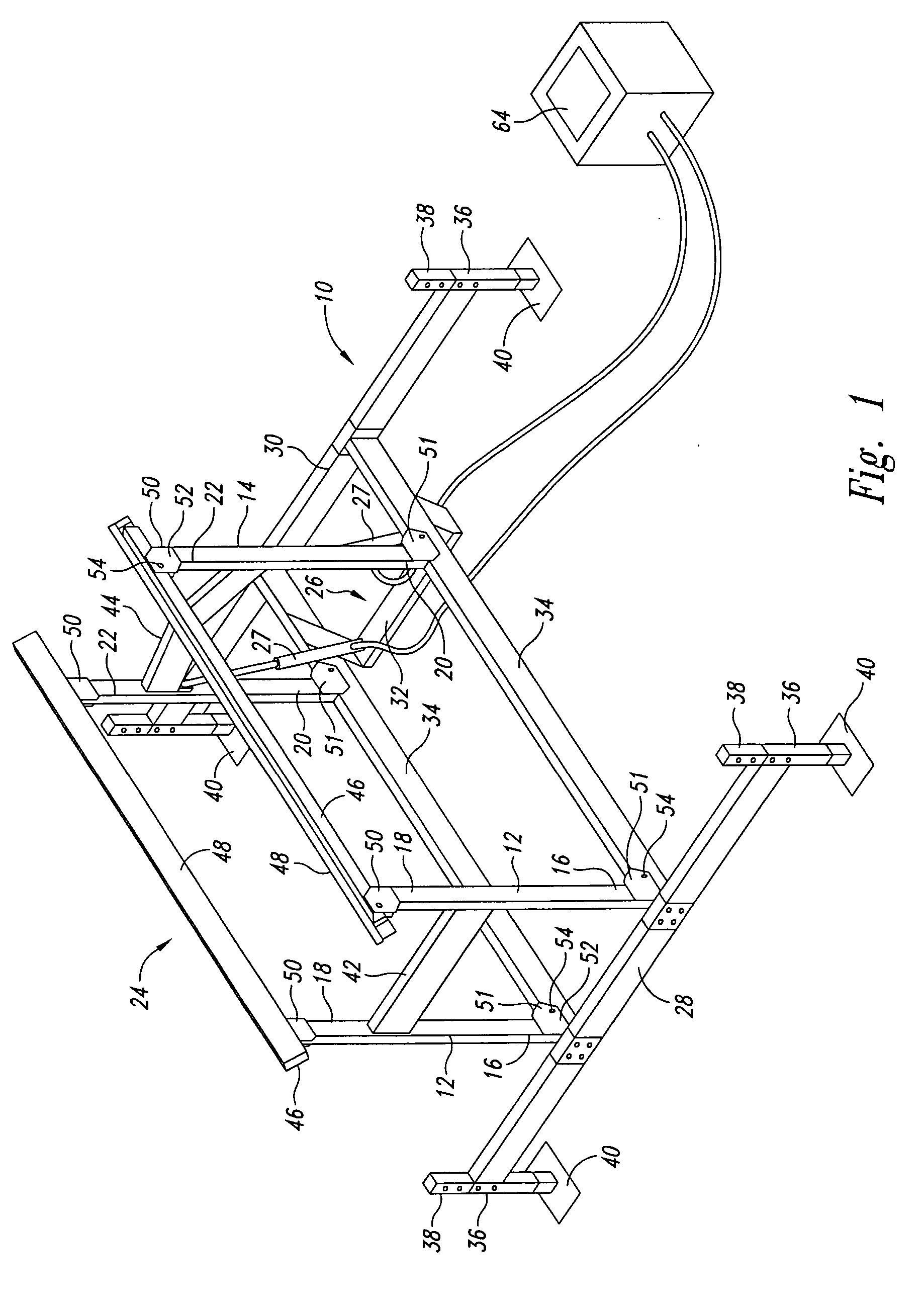
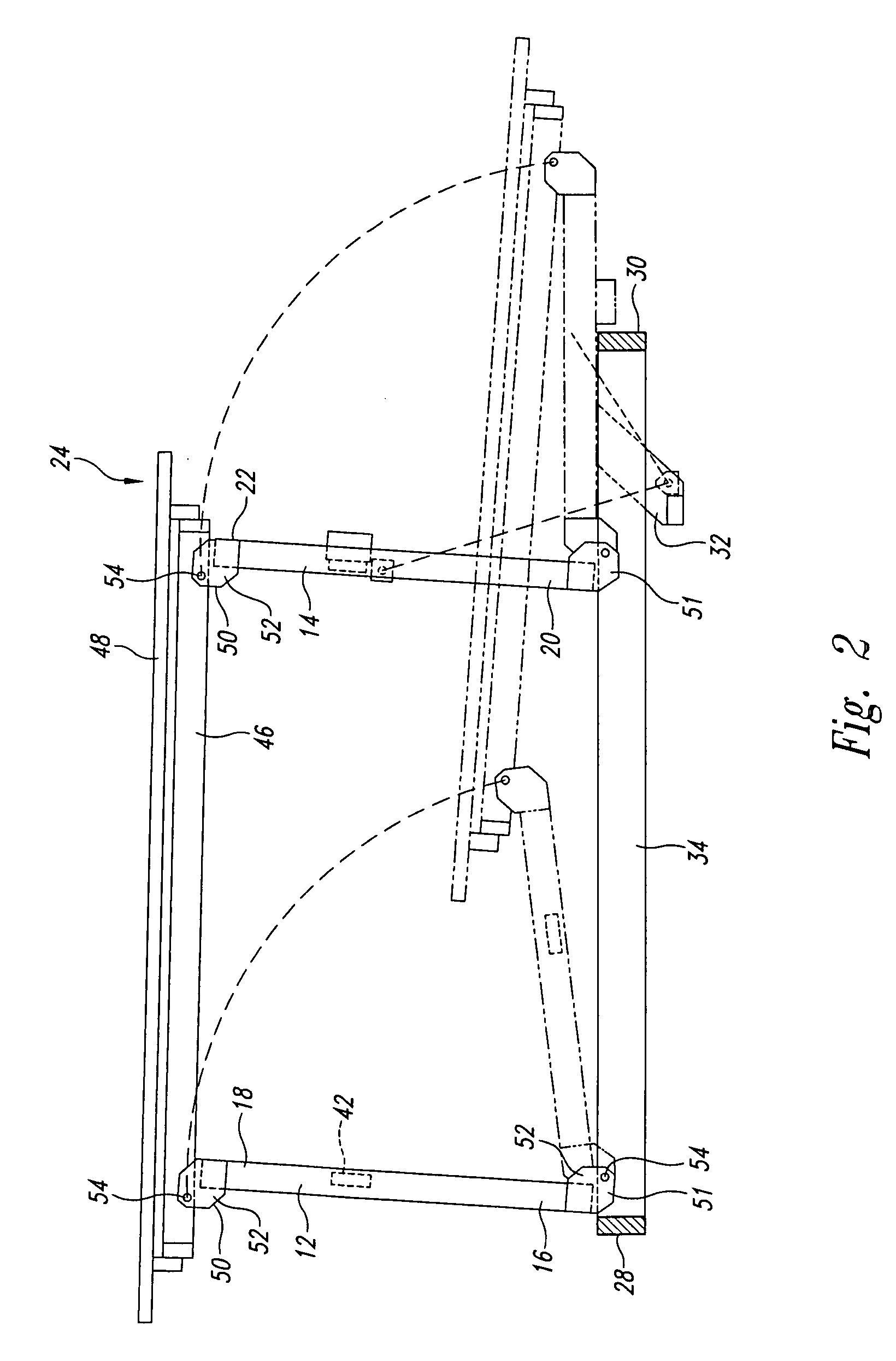
[0029] This description illustrates aspects of the invention, and describes embodiments of the invention. This description is not intended to be exhaustive, but rather to inform and teach the person of skill in the art who will come to appreciate more fully other aspects, equivalents, and possibilities presented by the invention. The scope of the invention is set forth in the claims, which alone limit its scope.

[0030] The embodiments are set forth in the following description and in FIGS. 1 through 12. One skilled in the art will understand that the present invention may be practiced without using all of the details described herein. In the following description, it is understood that a watercraft includes any vehicle that is at least partially waterborne, including boats and similar vessels, but may also include amphibious vehicles, including various amphibious automobiles or aircraft. Moreover, in the description that follows, it is understood that the figures related to the vari...


PUM


Abstract

A watercraft lift with translating bunks supported by a base frame and having rollers mounted to the base frame to initially raises the watercraft upward when driven onto the lift sufficiently to be positioned above the bunks when in their lowered position and thereby permit operation of the lift in water too shallow for use of the bunks by themselves. The rollers are positioned relative to the translating bunks such that when the bunks are in their lowered position and the lift is used in sufficiently shallow water, the watercraft driven onto the lift initially engages the rollers, which lift the watercraft upward above the height when floating in the water and above the height of the bunks. The translating bunks are then used to lift the watercraft off of the rollers and upward to a raised position above the water.

Description

CROSS REFERENCE TO RELATED APPLICATION [0001] This application claims priority benefit of provisional application Ser. No. 60 / 621,520 filed Oct. 25, 2005.FIELD OF THE INVENTION [0002] The invention generally relates to a watercraft lift which reduces the minimum water depth requirement for free-standing boat lifts. BACKGROUND OF THE INVENTION [0003] The use of watercraft lifting devices is well known. A watercraft may be subject to several difficulties if moored within the water: damage to the watercraft may occur when wave action or other in-water forces cause the hull of the watercraft to strike adjacent in-water structures such as docks or seawalls; damage may also result from longer term effects such as vegetative buildup on the hull of the watercraft. Watercraft lifting devices alleviate these potential hazards by allowing the watercraft user to lift the watercraft from a position in the water to a position where the watercraft is wholly above the water. The watercraft lift thu...

Claims


Application Information

Patent Timeline
Patent Type & Authority Applications(United States)
IPC IPC(8): B63C3/06
CPCB63C3/06B63C3/12
Inventor HEY, KENNETH E.
Owner SUNSTREAM CORP
Why Eureka
Try Eureka