
Filter retrieval catheter system, and methods

Inactive Publication Date: 2006-07-06
CORDIS CORP
View PDF24 Cites 47 Cited by
  • Summary
  • Abstract
  • Description
  • Claims
  • Application Information

AI Technical Summary

Benefits of technology

[0011] The retrieval system of the present invention is capable of retrieving a filter when approaching from either direction. In other words, the present catheter-based retrieval system can be inserted through the femoral artery and approach the filter from the caudal direction to retrieve the filter, or through the jugular or brachial artery and approach the filter from the cranial direction, to retrieve the filter. This versatility is provided for approaching the filter from either direction, but enables the movement of the filter during retrieval to be in either direction. Accordingly, the filter can be pulled in the direction of movement that the filter does not resist, regardless of the direction from which the catheter-based retrieval system approaches the filter.
[0012] One example of a retrieval catheter system according to the present invention thus allows a filter to be designed to resist movement in the cranial direction, while still permitting retrieval by approaching the filter with a catheter-based retrieval system from either the cranial direction or the caudal direction.
[0013] In operation of a vascular filter retrieval system, the system may provide for “pulling” the filter a slight distance in the caudal direction to retract the filter anchors or barbs from engagement with the vessel, before “capturing” the filter within the catheter system, and then retrieving the catheter system and captured filter from whichever access point was selected, and thus in whichever direction is desired. This flexibility of approach may provide greater therapeutic options for treatment of patients.

Problems solved by technology

However, this approach may not be desirable, if the particular filter is designed to resist movement in the cranial direction.

Method used


Image

  • Filter retrieval catheter system, and methods
  • Filter retrieval catheter system, and methods
  • Filter retrieval catheter system, and methods

Examples


Embodiment Construction

[0025] The following description of the preferred embodiments of the present invention is merely illustrative in nature, and as such it does not limit in any way the present invention, its application, or uses. Numerous modifications may be made by those skilled in the art without departing from the true spirit and scope of the invention.

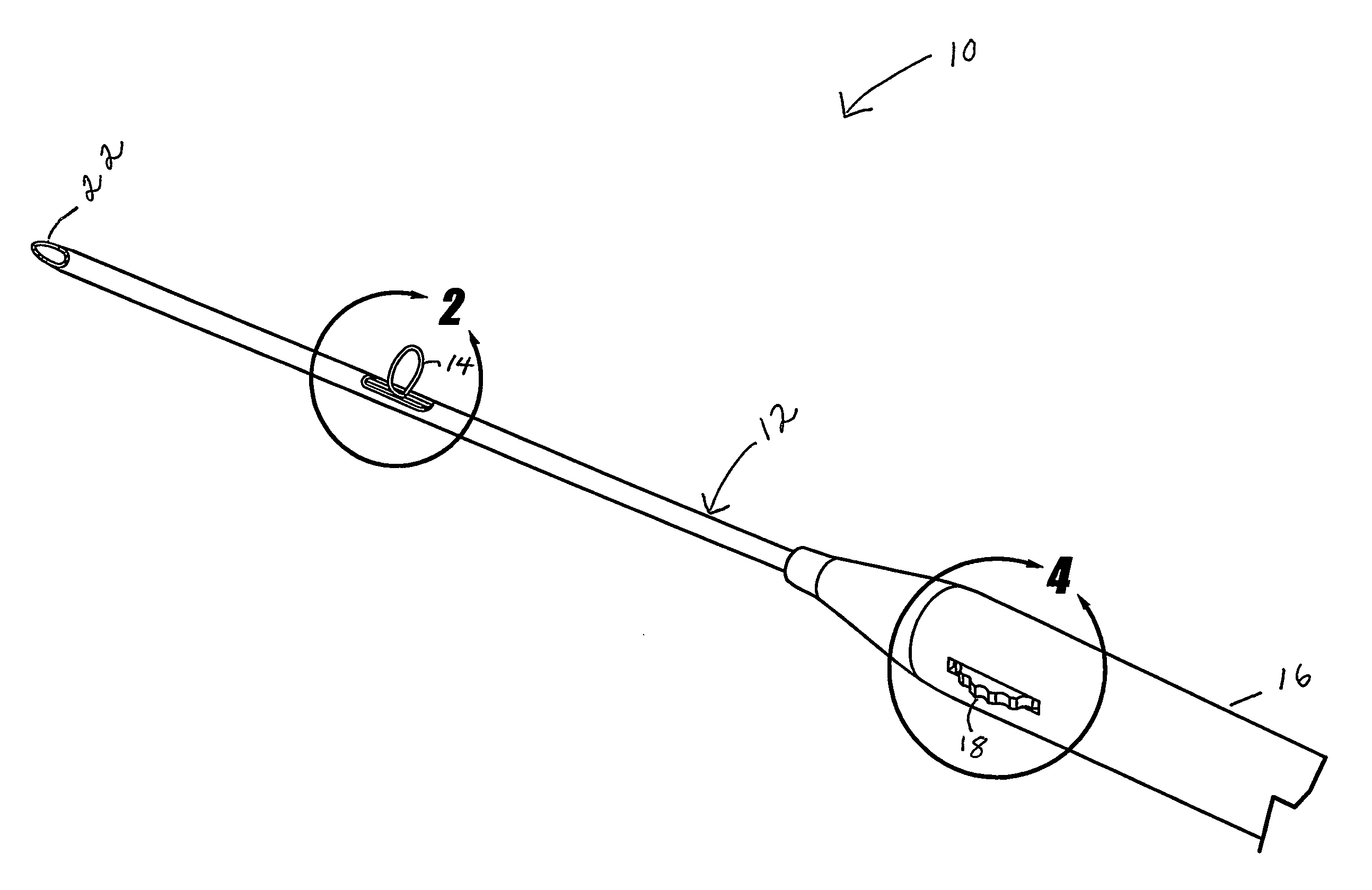
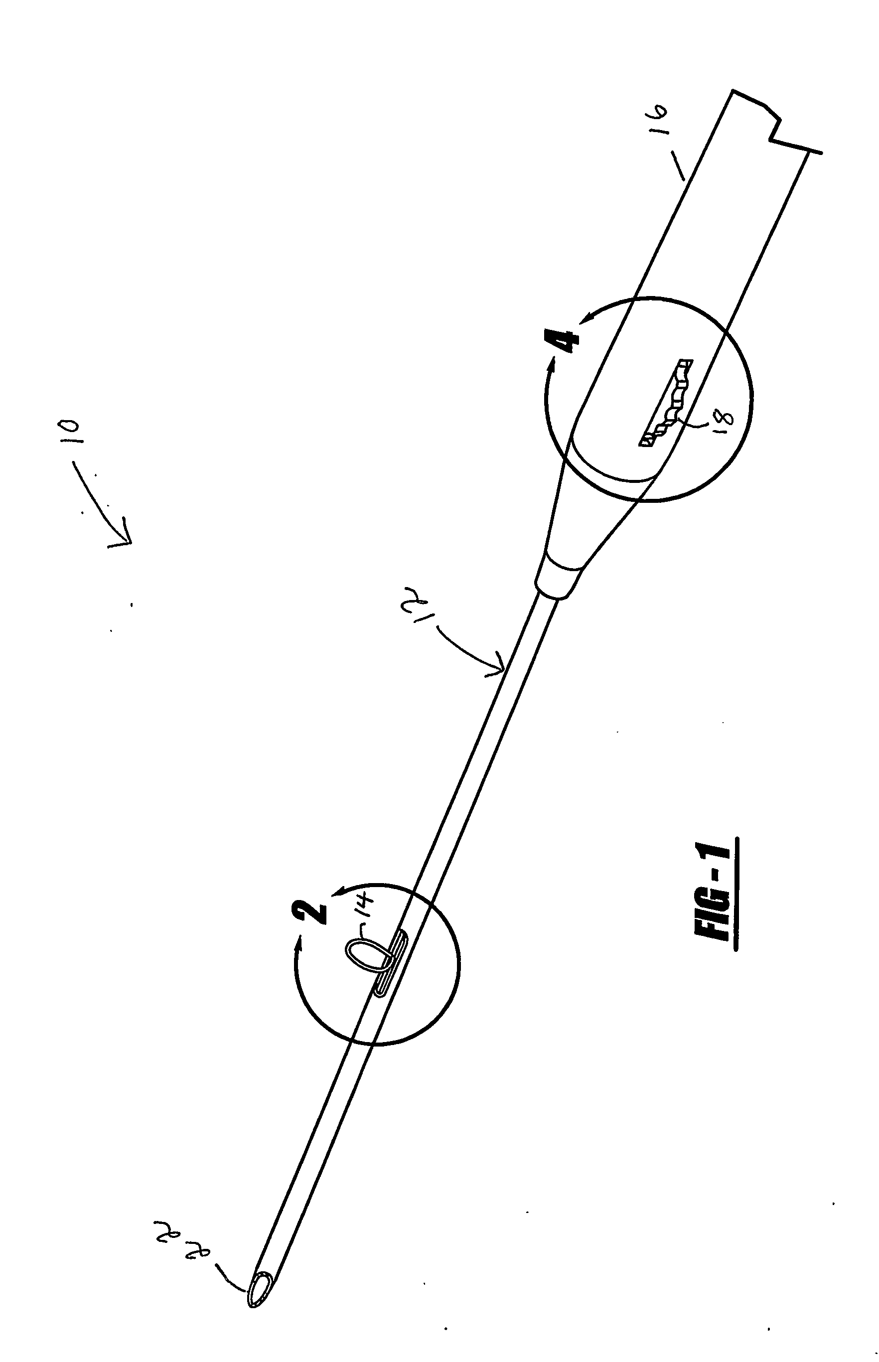
[0026] One possible arrangement of a filter retrieval system of the present invention is shown in the drawings. Filter retrieval system 10 includes a shaft 12, a retrieval element 14, and a handle 16 with an actuator 18.

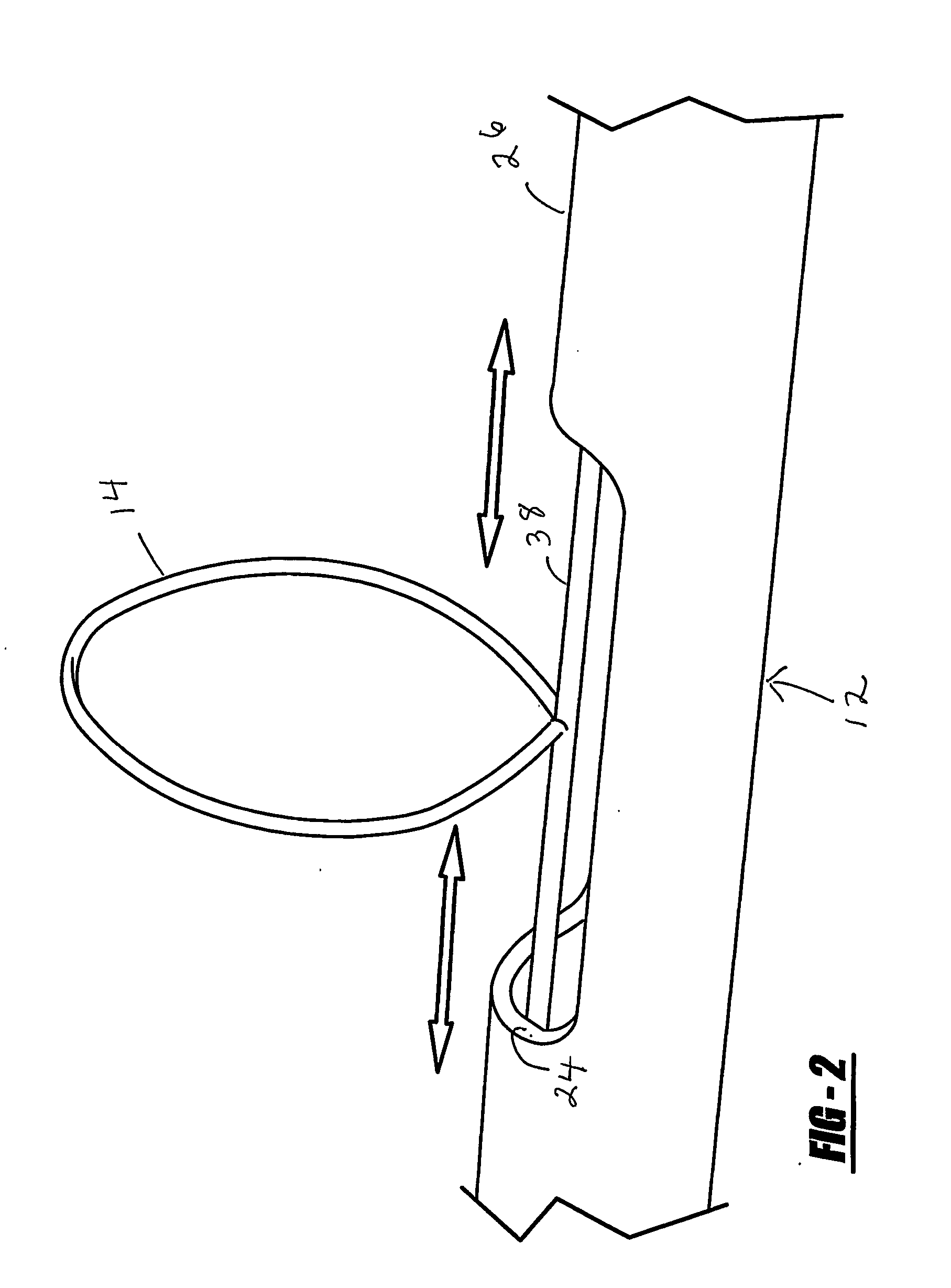
[0027] The shaft 12 may be catheter-based, and has a proximal and a distal end 20 and 22. The shaft 12 has an opening 24 in its sidewall 26 positioned a distance from the shaft distal end 22. In addition, the shaft 12 may define a lumen or passage 28 from its proximal end 20 to its distal end 22, or at least near its distal end 22. The shaft preferably has an optimum selection of characteristics, including flexibility, column stren...


PUM


Abstract

A filter retrieval system for retrieving a previously implanted medical filter, and methods of using the retrieval system, are disclosed. The filter retrieval system has a flexible shaft, a retrieval element, and a handle with an actuator. The flexible shaft may be catheter-based, and has a proximal and a distal end, and has an opening near its distal end. The handle is affixed to the shaft near the proximal end of the shaft, and the actuator is adapted to manipulate the retrieval element. When an operator manipulates the actuator, the retrieval element is adapted to protrude slightly from the shaft opening. As the actuator is operated, the retrieval element can grasp or hook or otherwise engage a portion of the filter, and then pull the filter in through the opening into a passage or lumen of the catheter shaft. The retrieval system may be capable of retrieving a filter in either a proximal or a distal direction as desired.

Description

CROSS-REFERENCE TO RELATED APPLICATION [0001] This application claims priority of U.S. Provisional Patent Application No. 60 / 444,320 filed Jan. 31, 2003.BACKGROUND AND SUMMARY OF THE INVENTION [0002] 1. Technical Background [0003] The present invention generally relates to a catheter system to retrieve a filter which has been previously implanted in a body passage for medical treatment of a patient. [0004] 2. Discussion [0005] Many different types of filters may be implanted in various body passages for medical treatment of a patient. The present invention will be described by using the specific example of a vascular filter for implantation in a blood vessel, and an example of one particular type of filter retrieval system for retrieving a vascular filter. However, it should be understood that the present invention is not limited to vascular applications, but rather relates to implantable filters for use in any medically suitable type of body passage, for example, the vascular syste...

Claims


Application Information

Patent Timeline
IPC IPC(8): A61B17/26A61B17/22A61F2/01A61LA61M29/00
CPCA61B17/221A61B17/32056A61B2017/22035A61F2/01A61F2002/011A61F2230/005A61F2/011
Inventor FLEMING III, JAMES A.
Owner CORDIS CORP
Learn More