Quick-change tools

a technology of tools and tools, applied in the field of quick-change tools, can solve the problems of substantial time, substantial chance of parts being lost, and difficulty in changing saw blades or other rotatable tool implements, and achieve the effect of simple, safe and reliabl

Inactive Publication Date: 2006-07-13
BACULY ERIC J
View PDF23 Cites 54 Cited by
  • Summary
  • Abstract
  • Description
  • Claims
  • Application Information

AI Technical Summary

Benefits of technology

[0008] The invention provides a simple, safe and reliable mechanism for achieving quick changing of tool implements on a shaft, post or handle. The

Problems solved by technology

As a result, changing of saw blades or other rotatable tool implements can be difficult and require a substantial amount of time.
Further, because a nut or bolt, and at least one other element such as a washer or stabilizer must be completely removed from the shaft or arbor in order to allow changing of the saw blade or other rotatable tool implements, there is a substantial chance that parts could become lost (e.g., fall in a pile of sawdust) during the changing of the blade or other rotatable tool implement.
While this mechanism allows quick removal of a saw blade or other rotatable tool part from a shaft, the mechanism is relatively complex and is believed to be undesirable because it relies on coil

Method used


Image

  • Quick-change tools
  • Quick-change tools
  • Quick-change tools

Examples


Embodiment Construction

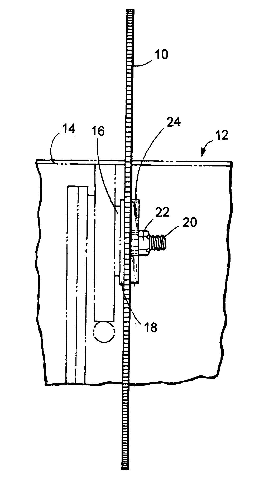
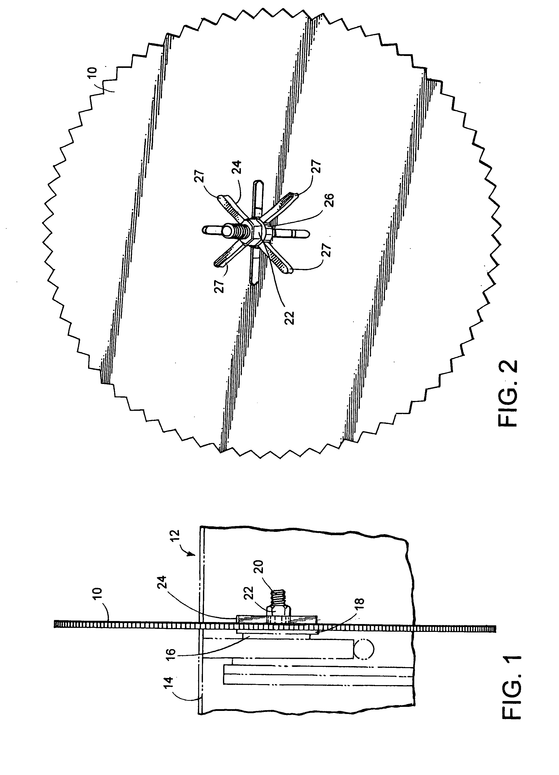
[0025] Shown in FIG. 1 is a circular saw blade 10 (work implement) mounted on a table saw 12 having a table top 14 and a power driven rotatable shaft 16. Rotatable shaft 16 includes an annular flange 13 and a threaded connector 20. Blade 10 is located immediately adjacent annular flange 18, and a stabilizing washer adapted to be received on threaded end portion 20 of rotatable shaft 16 is located immediately adjacent blade 10. Fastener nut 22 is tightened onto threaded end portion 20 of shaft 16 to securely retain blade 10 and a one-piece stabilizing washer 24 between annular flange 18 and nut 22.

[0026] As shown in FIG. 2, stabilizing washer 24 includes a central hub portion 26 which may be substantially circular in shape, and a plurality of projecting arms 27 which extend radially away from hub portion 26. Arms 27 are integral with and rigidly connected to central hub portion 26, i.e., arms 27 are not movable with respect to hub portion 26.

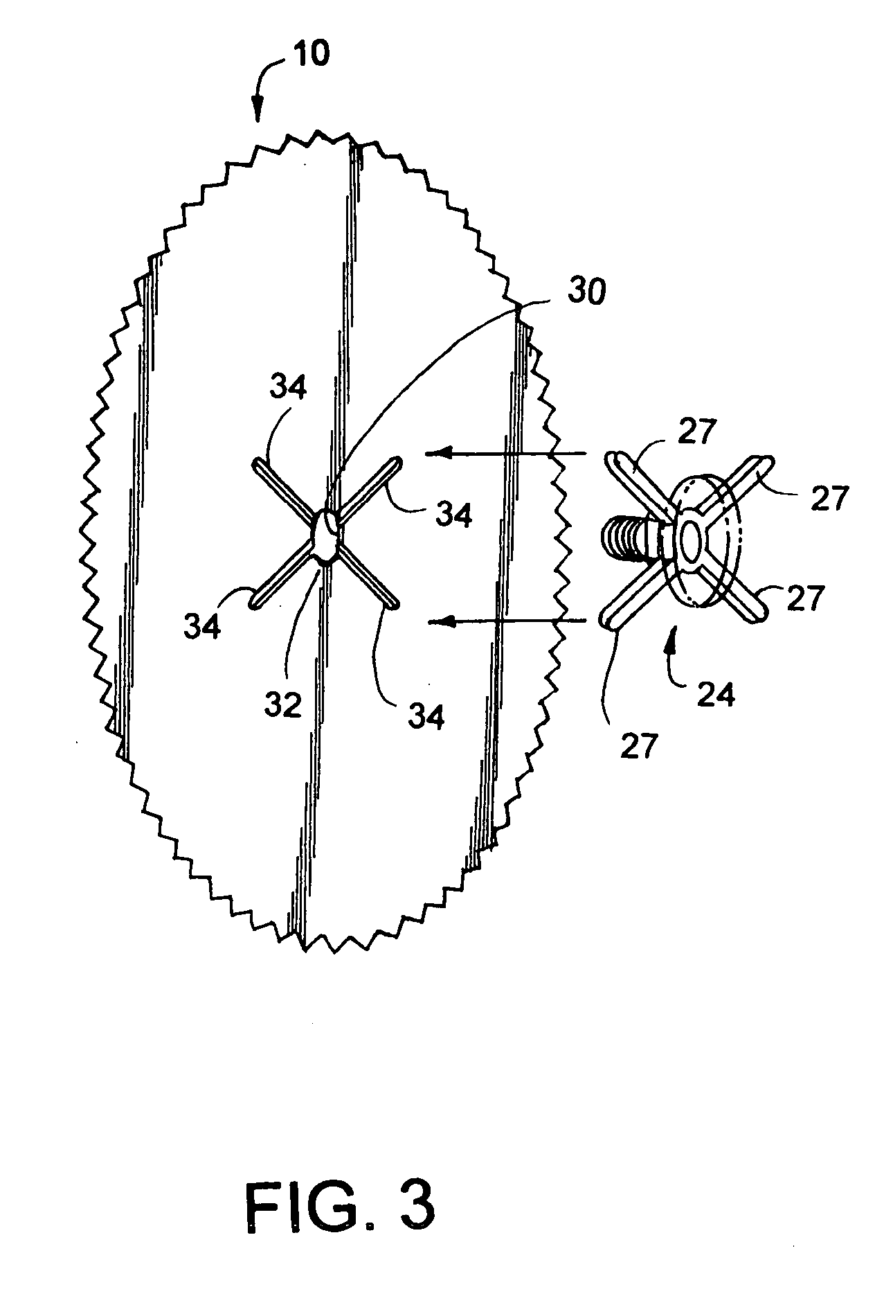
[0027] As shown in FIG. 3, blade 10 incl...


PUM


Abstract

A tool having a quick-change mechanism for replacing tool implements on a shaft, post or handle comprising a shaft, post or handle having a flange and a threaded connector. The tool further includes a tool implement adapted to be received on the shaft, post or handle adjacent thc flange. The tool also includes a stabilizer washer adapted to be received on the shaft, post or handle adjacent the work implement. A threaded fastener is adapted to be threaded onto the threaded connector of the shaft, post or handle whereby the tool implement and the stabilizer washer are retained on the shaft, post or handle by the fastener, and wherein the tool implement and the stabilizing washer are configured to allow removal of the tool implement without removing the fastener from the shaft, post or handle.

Description

FIELD OF THE INVENTION [0001] This invention relates to mechanisms for attachment and removal of tool implements on power tools or hand tools, and more particularly to mechanisms that facilitate quick changing of tool implements, such as lawn mower blades, saw blades, sander discs, grinder, scraper blades, wheels, and the like. BACKGROUND OF THE INVENTION [0002] Changing of rotating implements on power tools, such as circular saws, table saws, etc., generally requires unscrewing a nut or bolt which holds the blade or other tool implement on a rotatable shaft or arbor. The mechanism for attaching the rotatable tool part to the shaft generally comprises a plurality of components such as nuts, bolts, washers, stabilizers and the like. Often, all of these components must be completely removed from the shaft to facilitate removal of a saw blade or other rotatable tool implements from the shaft. As a result, changing of saw blades or other rotatable tool implements can be difficult and re...

Claims


Application Information

Patent Timeline
IPC IPC(8): B23D45/16A01D34/00B27B5/32
CPCA01D34/001A01D34/82A01D2101/00B24B45/006B27B5/32Y10T83/9379
Inventor BACULY, ERIC J.
Owner BACULY ERIC J
Why Eureka
Try Eureka