Sealed honeycomb structure and method of producing the same
a honeycomb and sealing technology, applied in the field of sealing or plugged honeycomb structure, can solve the problems of easy cracking in this portion, and achieve the effects of improving strength, adhesion and thermal shock resistan
Active Publication Date: 2006-07-13
NGK INSULATORS LTD
View PDF5 Cites 25 Cited by
- Summary
- Abstract
- Description
- Claims
- Application Information
AI Technical Summary
Benefits of technology
[0006] The present invention is characterized by providing a plugged honeycomb structure having further improved streng
Problems solved by technology
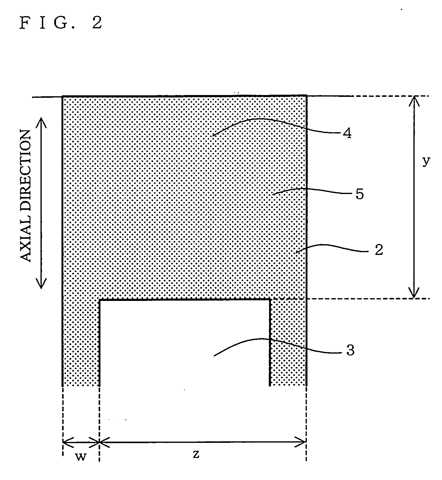
However, since various kinds of stress is prone to be applied on, for example, an interface portion 5 between t
Method used
View moreImage
Smart ImageViewing Examples
Examples
 PUM
| Property | Measurement | Unit |
|---|---|---|
| Temperature | aaaaa | aaaaa |
| Fraction | aaaaa | aaaaa |
| Fraction | aaaaa | aaaaa |
Abstract
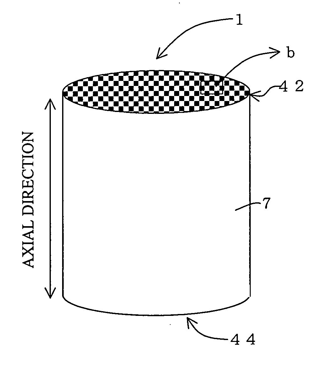
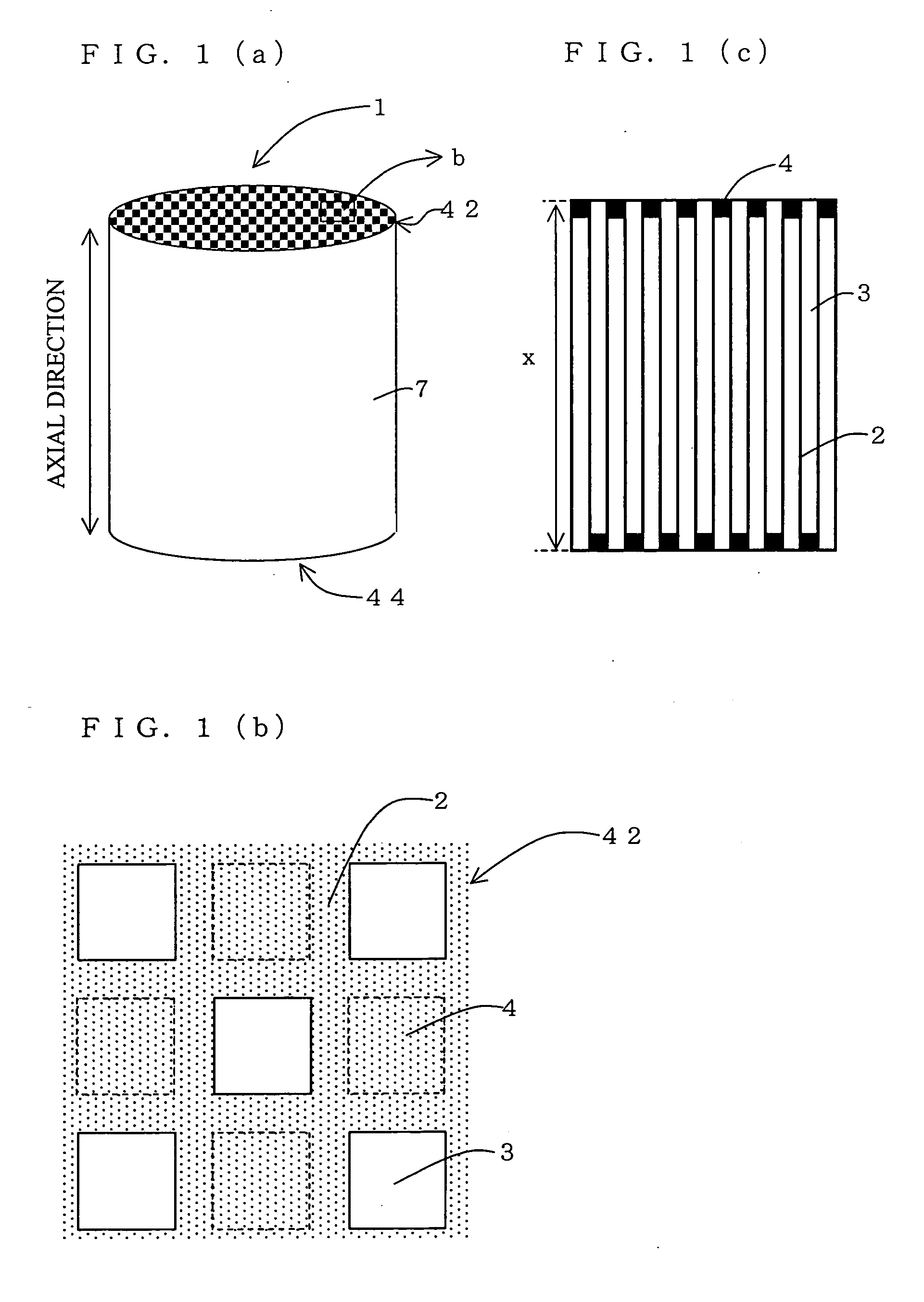
There is provided a plugged honeycomb structure 1 including: partition walls 2 disposed so as to form a plurality of cells 3 extending from one end face 42 to the other end face 44 in the axial direction, and plugged portions 4 disposed so as to plug the cells 3 at one of the end faces, and a production method thereof. In this honeycomb structure 1, the plugged portions 4 and partition walls surrounding the plugged portions are unitarily formed. The production method includes a forming step, a plugging step for filling a plugging material, and a firing step. The plugging material contains solid particles capable of unitarily joining with at least one kind of solid particles contained in a forming raw material in a firing step. A ratio of a dimensional change (%) upon forming the partition walls out of the partition wall-forming material to a dimensional change (%) upon forming the plugged portions out of the plugging material is controlled to be within the range of 0.7% to 1.3 in the firing step. There is provided a plugged honeycomb structure having further improved strength, adhesion, and thermal shock resistance between partition walls and plugged portions and a production method thereof.
Description
TECHNICAL FIELD [0001] The present invention relates to a sealed or plugged honeycomb structure usable for an exhaust gas purification filter, a water treatment filter, and a separation membrane filter and a production method thereof. In particular, the present invention relates to a plugged honeycomb structure having high strength, adhesion, and thermal shock resistance between partition walls and plugged portions. BACKGROUND ART [0002] When a honeycomb structure is used as an exhaust gas purification filter, as shown in FIGS. 9(a) to 9(c), the honeycomb structure is generally used in the form of a plugged honeycomb structure 1 provided with porous partition walls 2 disposed in such a manner that a plurality of cells 3 are extending from one end face 42 to the other end face 44 in an axial direction and plugged portions 4 disposed in such a manner that each of the cells 3 is plugged at one of the two end faces. By employing such a form, fluid to be treated flowing into cells from o...
Claims
Login to View More Application Information
Patent Timeline
 IPC IPC(8): B01D46/00B01D46/24B28B11/00F01N3/022
CPCB01D46/0001Y10T428/24149B01D46/2451B01D46/2459B01D46/2466B01D46/247B01D46/2474B01D2046/2496B28B11/006F01N3/0222Y02T10/20Y10S55/05Y10S264/48Y10S55/30Y10S55/10B01D46/2444Y02T10/12B01D46/2498B01D46/2476B01D46/2482B01D46/24494
Inventor ICHIKAWA, YUKIHITONOGUCHI, YASUSHI
Owner NGK INSULATORS LTD
Features
- R&D
- Intellectual Property
- Life Sciences
- Materials
- Tech Scout
- Unparalleled Data Quality
- Higher Quality Content
- 60% Fewer Hallucinations
Learn More Browse by: Latest US Patents, China's latest patents, Technical Efficacy Thesaurus, Application Domain, Technology Topic, Popular Technical Reports.
© 2025 PatSnap. All rights reserved.Legal|Privacy policy|Modern Slavery Act Transparency Statement|Sitemap|About US| Contact US: help@patsnap.com


