

Cable cooling system
a cooling system and cable technology, applied in the direction of pressure vessels, container discharging methods, containers discharging from pressure vessels, etc., can solve the problems of reduced electrical transmission efficiency, complex systems, and high cost of electrical transmission, and achieve the effect of increasing the pressure of the coolan
- Summary
- Abstract
- Description
- Claims
- Application Information
AI Technical Summary
Benefits of technology
Problems solved by technology
Method used
Image

Examples
Embodiment Construction
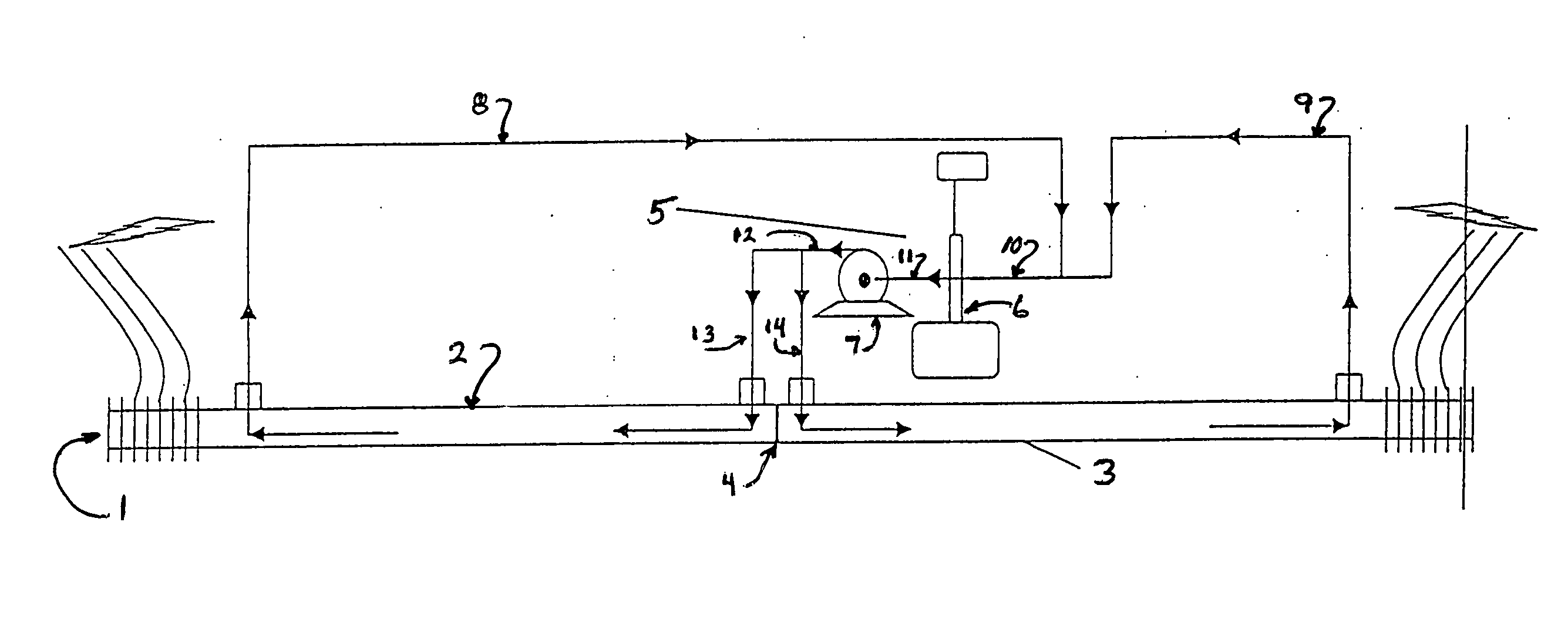
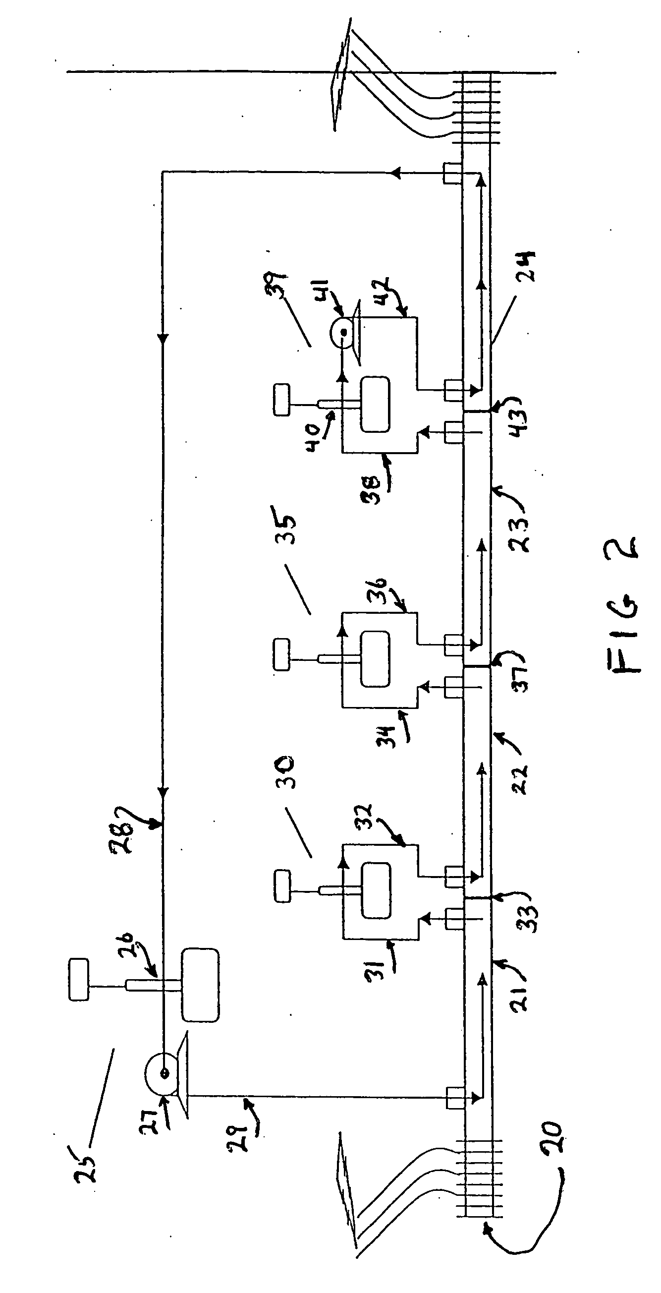
[0035] In general, the invention comprises a defined consolidation of cryocoolers or cryocoolers and pumps over an electrical transmission line or cable, and the positioning of such resulting cryocooler or cryocooler / pumping stations to receive coolant from and transmit coolant to different lengths of cable. The invention enables a reduction in the overall number of cryocoolers and pumps to service any given amount of transmission cable by both pressurizing and cooling the coolant, thereby increasing the effectiveness of the refrigeration transmittal to the cable.
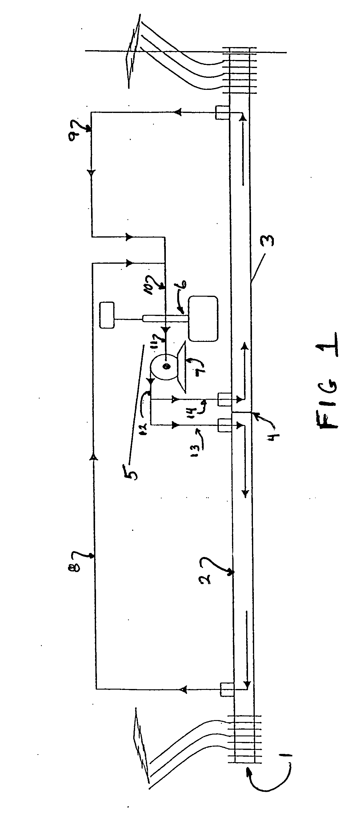
[0036] The invention will be described in greater detail with reference to the Drawings. Referring now to FIG. 1, there is illustrated a section of electrical transmission line 1 having a first length of cable 2 and a second length of cable 3 which, in the embodiment of the invention illustrated in FIG. 1, are separated by divider 4, although such a divider need not be employed. It is understood that over the course of the...
PUM
 Abstract
Description
Claims
Application Information