Hydraulic circuit for the control of a drive train

Inactive Publication Date: 2006-07-13
GETRAG GETRIEBE & ZAHNRADFABRIK HERMANN HAGENMEYER GMBH & CO KG
View PDF9 Cites 36 Cited by
  • Summary
  • Abstract
  • Description
  • Claims
  • Application Information

AI Technical Summary

Benefits of technology

[0052] Overall, it is advantageous, moreover, if, furthermore, a low-pressure circuit for cooling or lubrication is connected to the pump via a central valve.
[0053] By virtue of this measure, it is possible to connect the low-pressure circuit, too, to a central pump which also serves for supplying the high-pressure hydraulic branches.
[0054] In this case, it is particularly advantageous if the central valve is a proportional directional valve.
[0055] As a res

Problems solved by technology

This is generally not possible, for example, in conventional automated shift transmissions.
The use of flow valves for controlling the isolating clutches causes a valve hysteresis difficult to control in regulating terms and high valve damping.
This leads to losses in dynamics.
Due to t

Method used


Image

  • Hydraulic circuit for the control of a drive train
  • Hydraulic circuit for the control of a drive train
  • Hydraulic circuit for the control of a drive train

Examples


Example

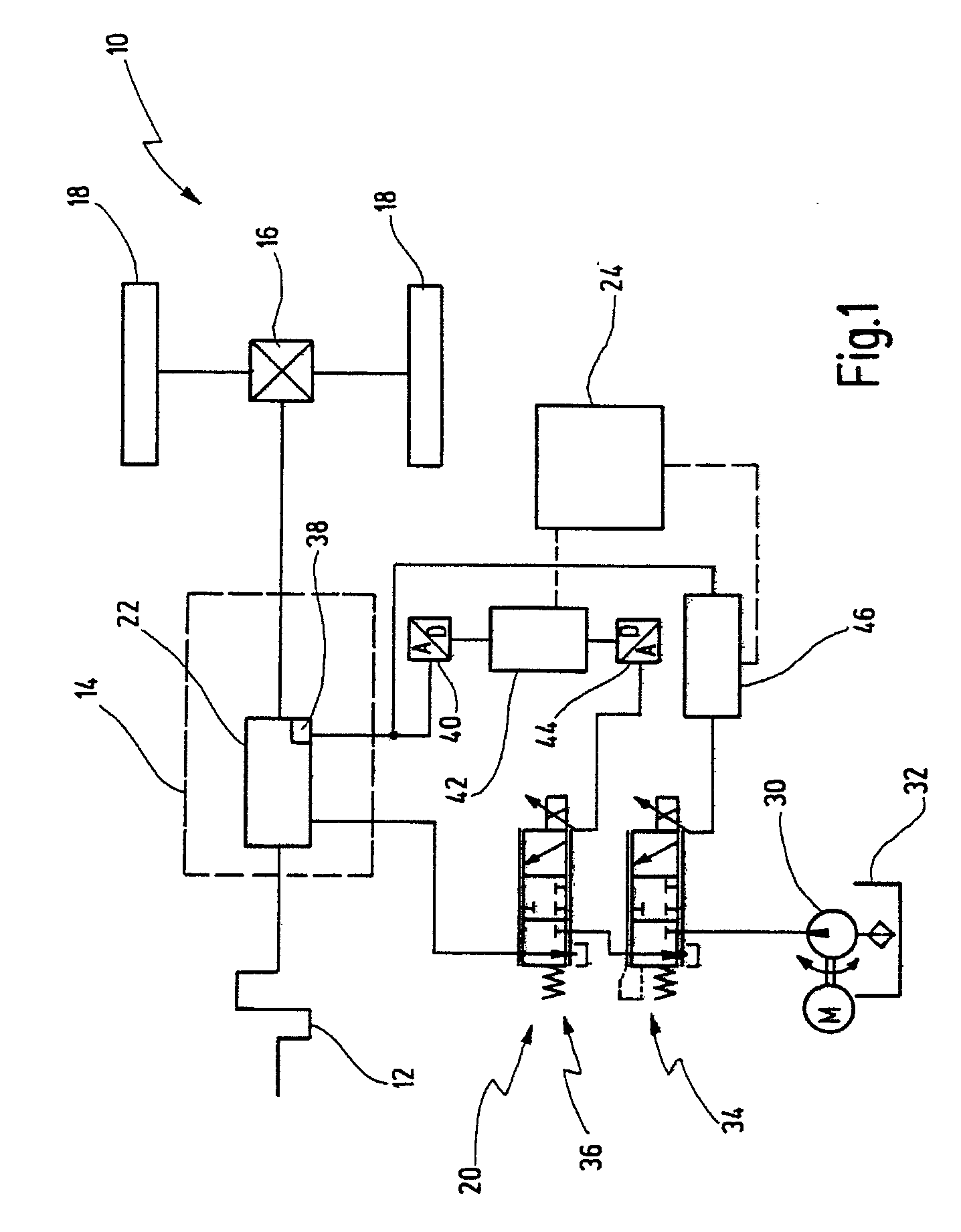
[0070]FIG. 1 illustrates a drive train for a motor vehicle 10 in diagrammatic form.

[0071] The drive train has an internal combustion engine 12, a transmission 14, a differential 16 and driven wheels 18.

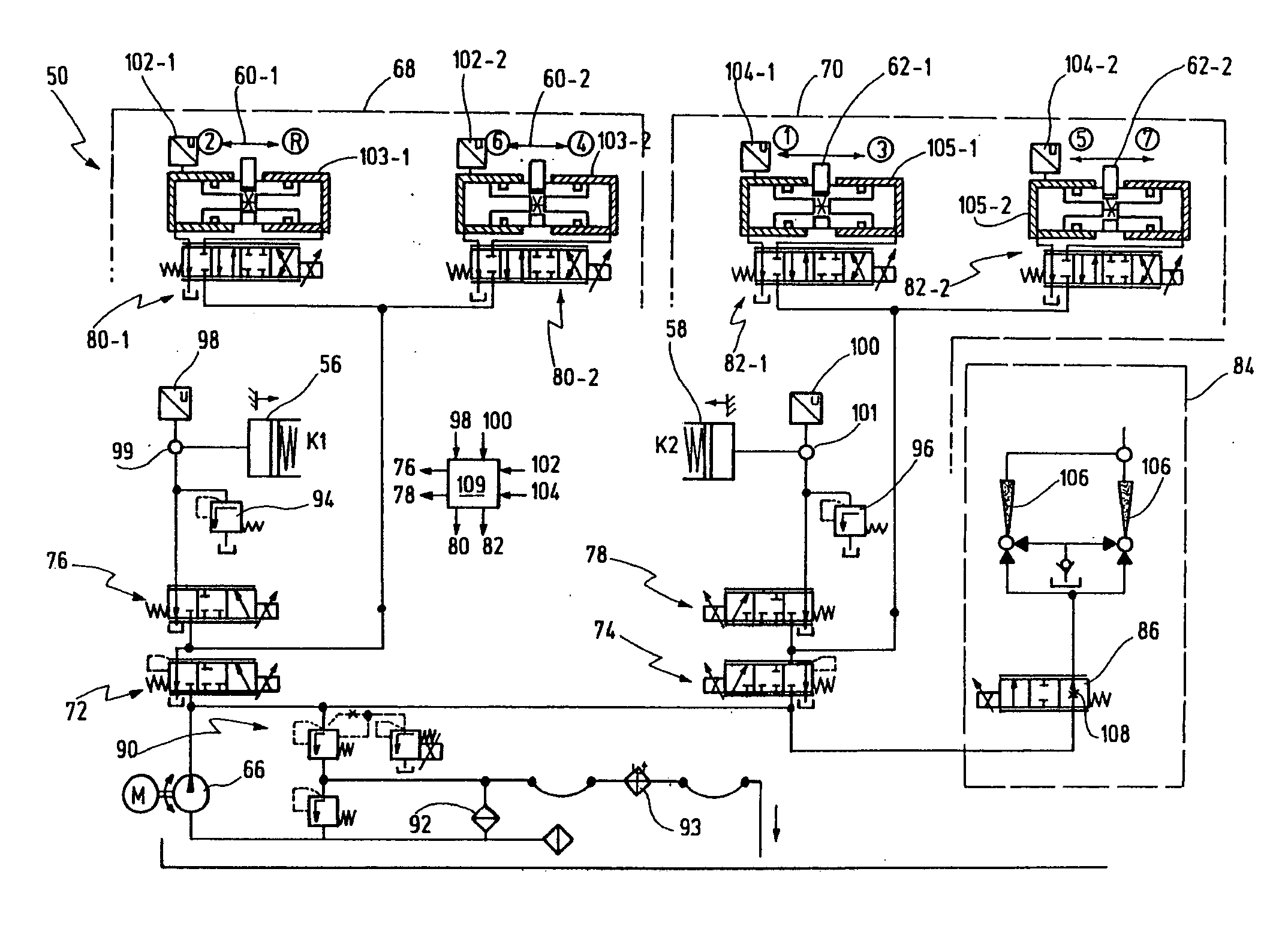
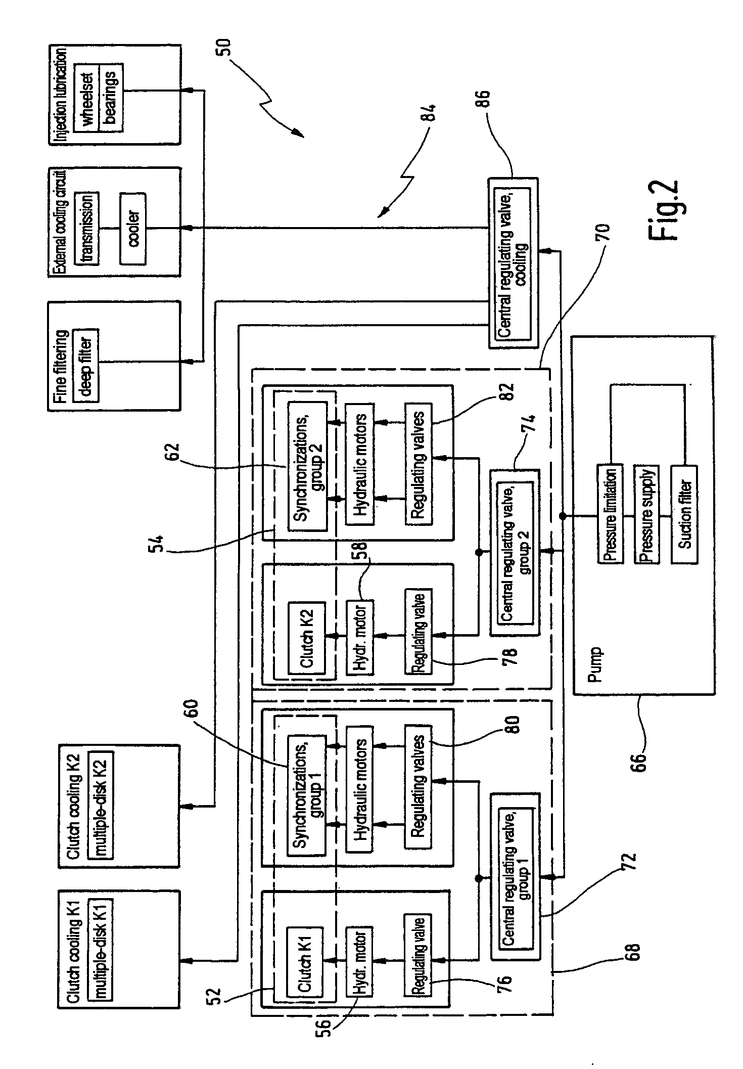
[0072] A hydraulic circuit 20 is provided for the control of the drive train, in particular of the transmission 14. Of the hydraulic circuit 20, only a detail is shown, which serves for controlling a safety-relevant device 22 of the transmission 14.

[0073] The safety-relevant device may be, for example, an isolating clutch or a shift clutch of an automated shift transmission or of a double clutch transmission. It may also be, however, a variator of a continuously variable transmission or a variator of a toroidal transmission or the like.

[0074] A safety-relevant device is to be understood, in the present context, as meaning any device of the transmission 14, the faulty actuation of which may be detrimental to the operating safety of the motor vehicle 10.

[0075]FIG. 1 shows, furtherm...


PUM


Abstract

A hydraulic circuit for the control of a double clutch transmission which has two transmission groups, each with an isolating clutch and with a plurality of shift clutches for the engagement and disengagement of gear steps, the hydraulic circuit having for each transmission group a specific hydraulic branch connected to a pump in each case via a safety valve, and each hydraulic branch having in each case a clutch control valve for controlling the assigned isolating clutch and at least one shift control valve for controlling the assigned shift clutches. Here, the safety valves are designed in each case as proportional pressure regulating valves.

Description

CROSS-REFERENCE TO RELATED APPLICATIONS [0001] This application is a continuation of PCT / EP2004 / 001727 filed on Feb. 21, 2004. The entire disclosure of this application is hereby incorporated by reference in its entirety.BACKGROUND OF THE INVENTION [0002] The present invention relates to a hydraulic circuit for the control of a drive train of a motor vehicle and relates particularly to a hydraulic circuit for the control of a double clutch transmission which has two transmission groups, each with an isolating clutch and with a plurality of shift clutches for engaging and disengaging of gear steps, the hydraulic circuit having for each transmission group a specific hydraulic branch connected to a pump in each case via a safety valve, and each hydraulic branch having in each case a clutch control valve for controlling the assigned isolating clutch and at least one shift control valve for controlling the assigned shift clutches. [0003] Such a hydraulic circuit is known from DE 101 34 1...

Claims


Application Information

Patent Timeline
IPC IPC(8): F16H3/22F16H61/00F16H61/12F16H61/28F16H63/28
CPCF16H61/12F16H61/2807F16H61/688F16H63/18F16H63/28F16H2061/1204Y10T74/19326F16H2061/1224F16H2306/00F16H2061/1268F16H2061/1264F16H2061/0253F16H2061/122
Inventor PETRZIK, GUNTHER
Owner GETRAG GETRIEBE & ZAHNRADFABRIK HERMANN HAGENMEYER GMBH & CO KG
Why Eureka
Try Eureka