Air induction system with hydrocarbon trap assembly

a technology of hydrocarbon traps and air induction systems, which is applied in the direction of combustion-air/fuel-air treatment, separation processes, filtration separation, etc., can solve the problems of puck-like filter elements, affecting the quality of air in the air, and generating hydrocarbon emissions

Inactive Publication Date: 2006-07-13
NOVARES US ENGINE COMPONENTS INC
View PDF6 Cites 45 Cited by
  • Summary
  • Abstract
  • Description
  • Claims
  • Application Information

AI Technical Summary

Problems solved by technology

Evaporative hydrocarbon emissions emanating from the internal combustion engine itself, however, remain a significant source of pollution.
In practice, these puck-like filter elements suffer from several drawbacks, including durability, including susceptibility to damage as

Method used


Image

  • Air induction system with hydrocarbon trap assembly
  • Air induction system with hydrocarbon trap assembly
  • Air induction system with hydrocarbon trap assembly

Examples


Embodiment Construction

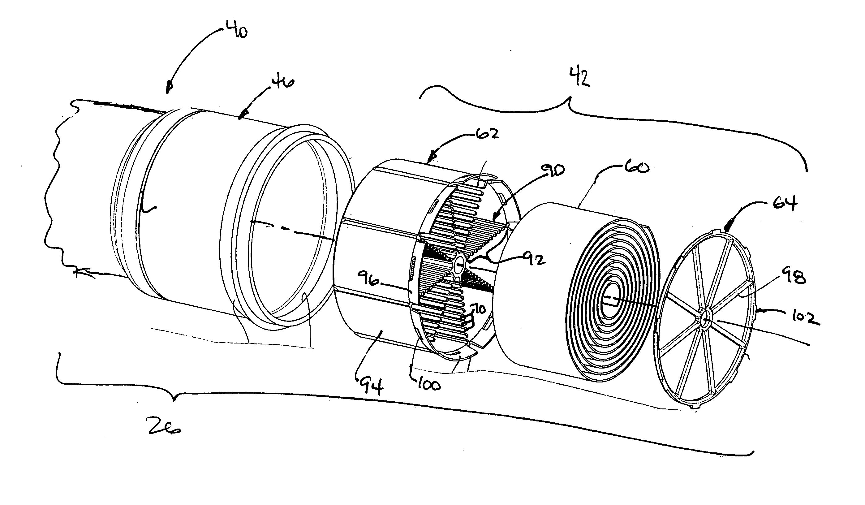
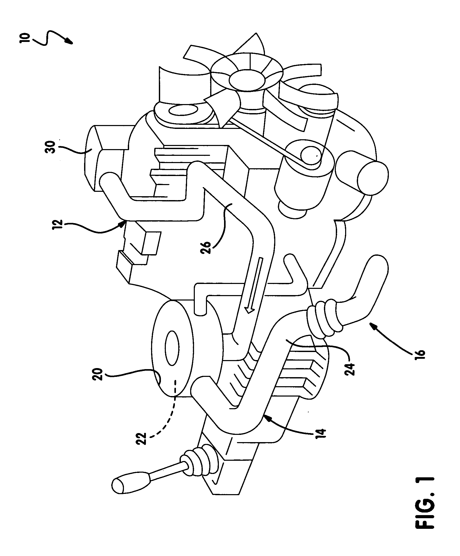
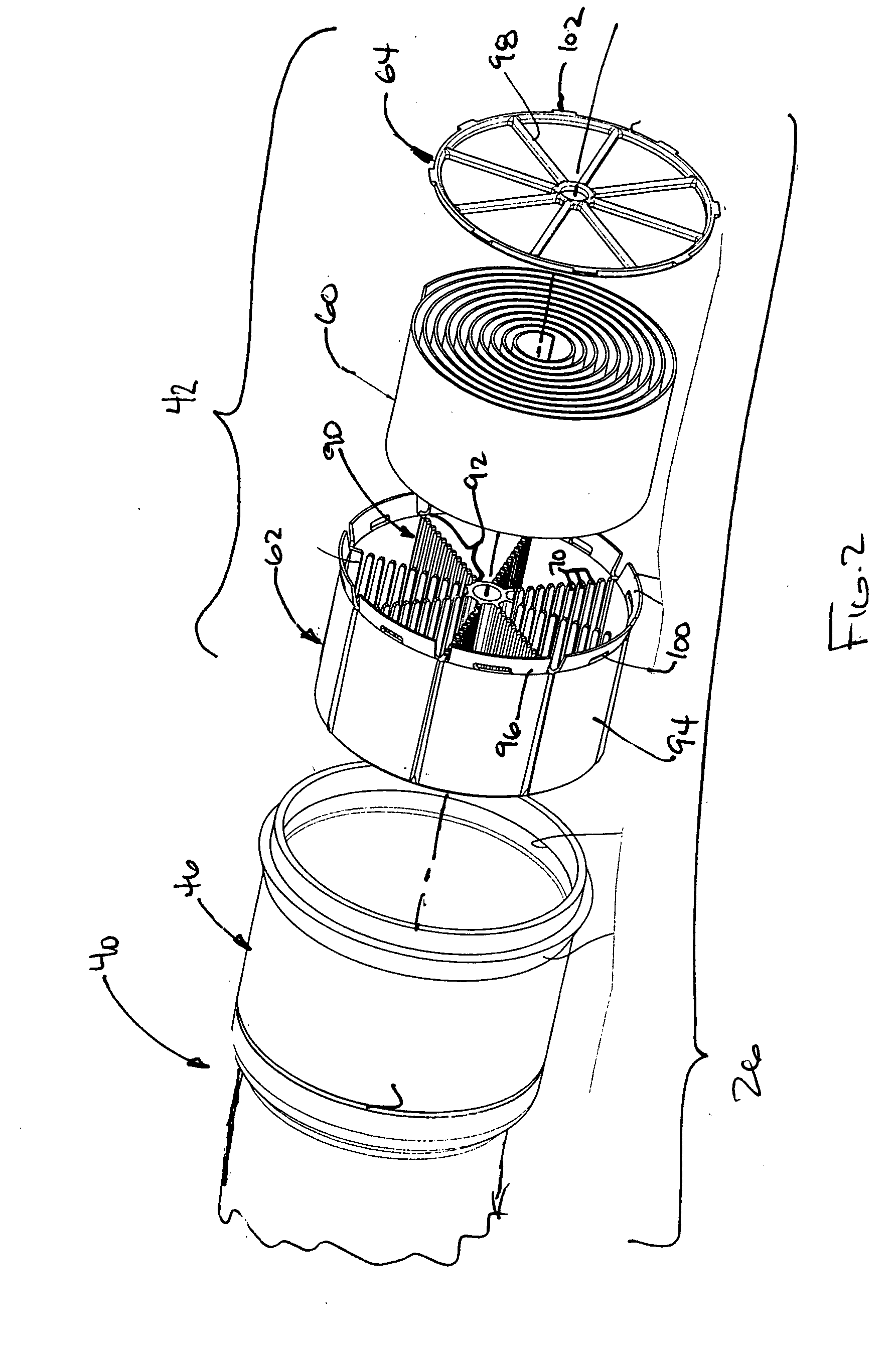
[0021] With reference to FIG. 1 of the drawings, an exemplary powertrain of a motor vehicle with an air induction system constructed in accordance with the teachings of the present invention is generally indicated at reference numeral 10. The powertrain 10 includes an engine 12 whose output is transmitted to a transmission 14. The engine 12 includes an air induction system 16 that routes air to the engine 12 for use in a combustion event.

[0022] The air induction system 16 includes an air filter housing 20, a primary air filter 22, an inlet duct 24 and a clean air duct 26. The air filter housing 20 includes an inlet which is coupled in fluid connection to the inlet duct 24 and an outlet which is coupled in fluid connection to the clean air duct 26. The primary air filter 22 is housed in the air filter housing 20 and filters dirt and debris from the air that is routed into the air filter housing 20 by the inlet duct 24. Filtered or clean air is routed to an engine intake manifold 30 ...


PUM

PropertyMeasurementUnit
Flow rateaaaaaaaaaa

Abstract

A hydrocarbon trap that includes a sheet paper element and a plurality of fingers. The paper element is at least partially formed of a material capable of adsorbing and desorbing gaseous hydrocarbons. The paper element is arranged into a plurality of adjacent sheet members. The fingers are disposed between and support adjacent pairs of the sheet members so that each adjacent pair of the sheet members forms a flow channel. A method for filtering gaseous hydrocarbons from an air flow is also provided.

Description

INTRODUCTION [0001] The present invention generally relates to air cleaners and more particularly to a hydrocarbon trap for reducing evaporative emissions from an internal combustion engine. [0002] Emissions regulations on devices powered by internal combustion engines, such as vehicles, motorized lawn / garden / farming equipment and hand-held outdoor power tools, have largely focused on two distinct types of emission sources: exhaust emissions discharged from the engine and evaporative emissions released from the fuel tank. Evaporative hydrocarbon emissions emanating from the internal combustion engine itself, however, remain a significant source of pollution. [0003] One proposed solution reducing evaporative emissions from an engine is described in U.S. Pat. No. 6,692,551. This proposed solution employs an adapter that is coupled to an air cleaner housing. The adapter includes a puck-like filter element that is positioned to intercept hydrocarbons before they migrate reversely from t...

Claims


Application Information

Patent Timeline
IPC IPC(8): B01D53/02
CPCB01D53/0415B01D53/0446B01D2253/102B01D2253/34B01D2257/702B01D2258/01B01D2259/4516B01D2259/4566F02M25/08F02M35/02F02M35/10019
Inventor CALLAHAN, DOUGLASVAN DE BOGERT, MARK
Owner NOVARES US ENGINE COMPONENTS INC
Why Eureka
Try Eureka