Adsorbent material for reducing hydrocarbon bleed emission in an evaporative emission control system

a technology of evaporative emission control and absorbent material, which is applied in the field of substrates, can solve the problems of increased vapor pressure in the fuel tank, potential for evaporative loss of fuel to the atmosphere, and certain limitations of the capacity and performance of the above-mentioned canister system

Pending Publication Date: 2022-07-07
BASF CORP
View PDF0 Cites 0 Cited by
  • Summary
  • Abstract
  • Description
  • Claims
  • Application Information

AI Technical Summary

Problems solved by technology

Evaporative loss of gasoline fuel from the fuel systems of motor vehicles powered by internal combustion engines is a major potential contributor to atmospheric air pollution by hydrocarbons.
During such periods (i.e., when parked), vehicle fuel systems may be subject to warm environments, which result in increased vapor pressure in the fuel tank

Method used


Image

  • Adsorbent material for reducing hydrocarbon bleed emission in an evaporative emission control system
  • Adsorbent material for reducing hydrocarbon bleed emission in an evaporative emission control system
  • Adsorbent material for reducing hydrocarbon bleed emission in an evaporative emission control system

Examples


example 1

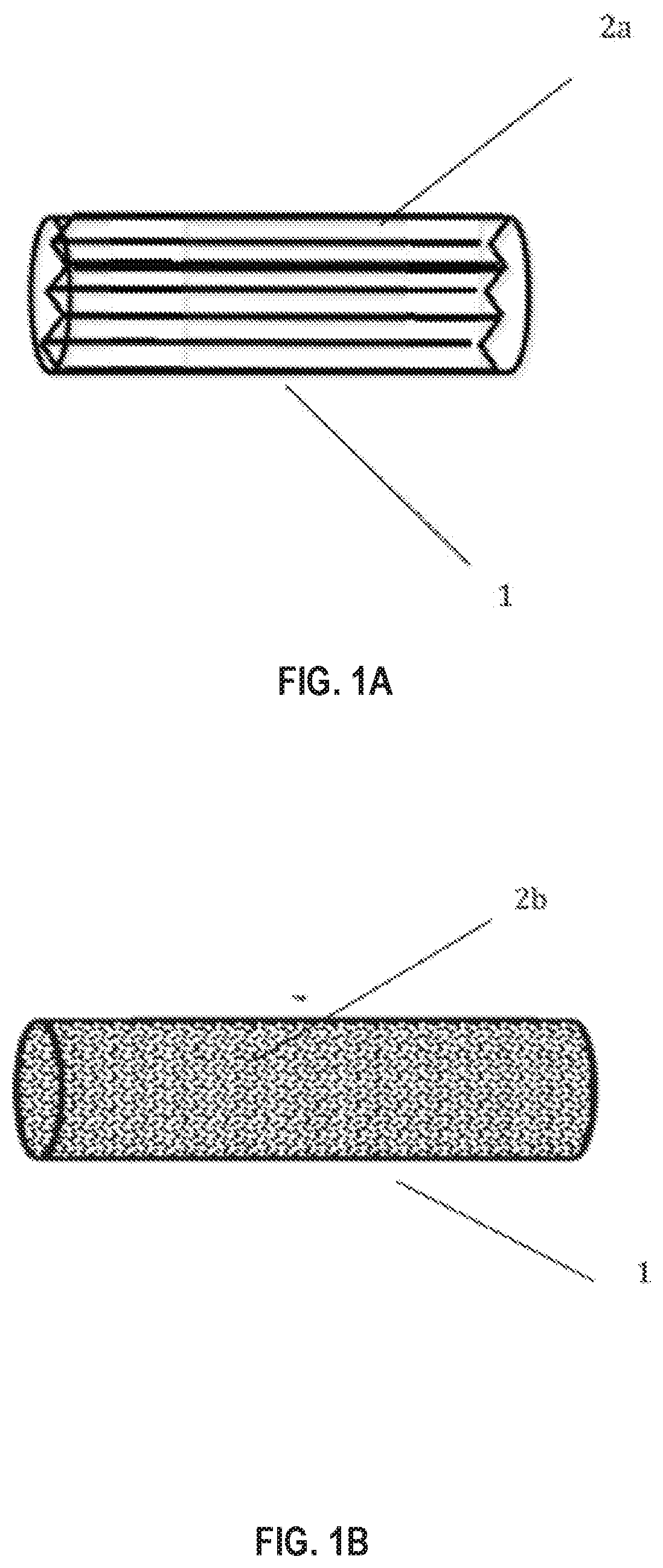
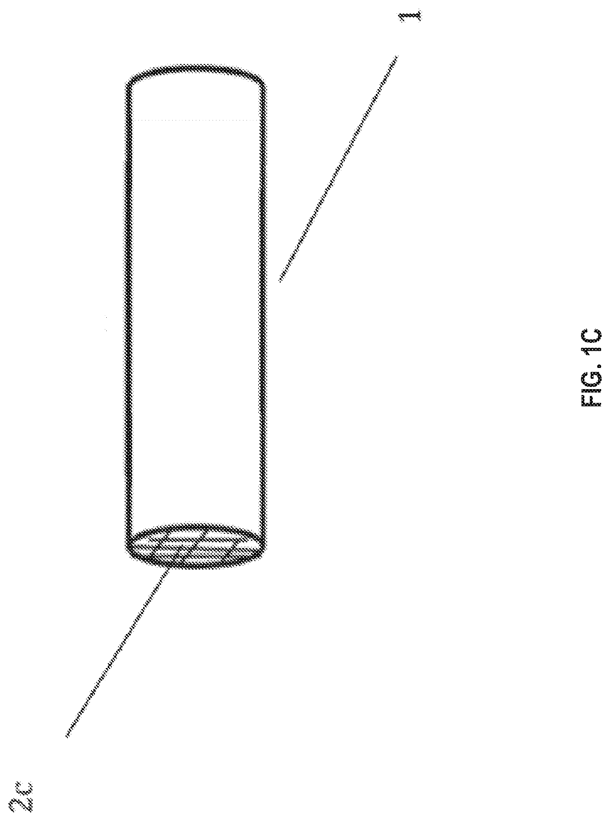
on of Monolith Coated with a Zeolite

[0103]298.8 g of water was mixed with Zeolite 3 from Example 5 (below) and the combination was mixed thoroughly with a Ross high-shear mixer. The resulting suspension was then milled with an Eiger continuous mill until the d90 particle size was 17.8 microns. 50.59 g of a 30% zirconium acetate solution and 2 drops of octanol were then mixed in to form the final slurry.

[0104]A cylindrical ceramic monolith substrate (230 cells per square inch) of 29×100 mm (cylinder diameter×length) was dipped into the slurry. Excess slurry was removed by clearing the channels using an air-knife operated at a pressure of 55 psi. The substrate was dried at 110° C. for 1 hour and then calcined in air at 300° C. for 3 hours. The final loading of the coating on the substrate was 1.76 g / in3.

example 2

nt of Pore Size Distribution

[0106]Nitrogen pore size distribution and surface area analysis were performed on Micromeritics TriStar 3000 series instruments. The material to be tested was degassed for a total of 6 hours (a 2-hour ramp to 300° C., then a hold at 300° C. for 4 hours, under a flow of dry nitrogen) on a Micromeritics SmartPrep degasser. Nitrogen BET surface area was determined using 5 partial pressure points between 0.08 and 0.20. The nitrogen pore size was determined using the BJH calculations and 33 desorption points.

[0107]FIG. 4A shows the pore size distribution of a beta zeolite (Zeolite 3 from Example 5) versus the commercially-available monolith carbon, and FIG. 4B shows the corresponding cumulative pore size distribution. In this graph can be seen the relatively lower amount of mesopores that are present in Zeolite 3, yet still has a significant amount of micropores.

example 3

nt of Butane Isotherms

[0108]A butane isotherm measurement measures the adsorbed amount of butane in a sample material as a function of the partial pressure of butane. Butane is introduced incrementally into the evacuated sample, allowed to reach equilibrium, and the adsorbed mass is measured. The procedure used for this is example is as follows: an approximately 0.1 g sample of material is degassed under vacuum at 120° C. for 960 minutes, and the butane isotherm was measured using a 3Flex High Resolution High-throughput Surface Characterization Analyzer. The adsorptive test gas used is butane and the backfill gas used is nitrogen. During the analysis, a temperature of 298 K is maintained with a circulating bath of a water and antifreeze mixture. Low pressure dose amounts are 0.5 cc / g up to 0.000000100 p / p0, and 3.0 cc / g up to 0.001 p / p0. An equilibration interval of 30 seconds is used up to 0.001 p / p0, and an equilibration interval of 10 seconds is used for the rest of the isotherm....


PUM

PropertyMeasurementUnit
Fractionaaaaaaaaaa
Thicknessaaaaaaaaaa
Fractionaaaaaaaaaa

Abstract

Disclosed in certain embodiments are hydrocarbon adsorbents and evaporative emission control systems incorporating the same to reduce hydrocarbon bleed emissions from fuel systems. In one embodiment, a hydrocarbon adsorbent structure comprises a zeolite having a silica-to-alumina ratio of at least 20.

Description

CROSS-REFERENCE TO RELATED APPLICATION(S)[0001]The present application claims the benefit of priority of U.S. Provisional Patent Application No. 62 / 836,121, filed on Apr. 19, 2019, the disclosure of which is hereby incorporated by reference herein in its entirety.TECHNICAL FIELD[0002]The present disclosure relates generally to hydrocarbon emission control systems, devices, and compositions for use in the same. More particularly, the present disclosure relates to substrates coated with hydrocarbon adsorptive coating compositions, evaporative emission control system components, and evaporative emission control systems for controlling evaporative emissions of hydrocarbons from motor vehicle engines and fuel systems.BACKGROUND[0003]Evaporative loss of gasoline fuel from the fuel systems of motor vehicles powered by internal combustion engines is a major potential contributor to atmospheric air pollution by hydrocarbons. Evaporative emissions are defined as emissions that do not originat...

Claims


Application Information

Patent Timeline
IPC IPC(8): B01J20/18B01J20/28B01J20/32B01D53/04
CPCB01J20/18B01D2259/4566B01J20/2803B01J20/28042B01J20/2808B01J20/3238B01D53/0407B01D2253/102B01D2253/1085B01D2253/25B01D2253/304B01D2253/308B01D2253/342B01D2257/7022B01D2259/4516B01J20/28004B01D53/02F02M25/0854B01D2257/702F02M25/089B01D53/04
Inventor ALDEN, LAIFRUETTINGER, WOLFGANGCHIN, STEVEN WESLEYLAPADULA, GERARD DIOMEDEMOINI, AHMAD
Owner BASF CORP
Why Eureka
Try Eureka