
Low permeation polymer fuel tank

a fuel tank and polymer technology, applied in the field of polymer fuel tanks, can solve the problems of fuel vapor permeating the walls of the polymer container, adding weight to the vehicle, and being subject to corrosion, so as to reduce the permeation, increase the dispersion pathway, and reduce the permeation

Inactive Publication Date: 2007-05-01
VISTEON GLOBAL TECH INC
View PDF25 Cites 22 Cited by
  • Summary
  • Abstract
  • Description
  • Claims
  • Application Information

AI Technical Summary

Benefits of technology

The present invention provides a way to reduce fuel evaporation and permeation from a polymeric fuel tank. This is achieved by coating the fuel tank with a secondary polymeric barrier layer that is solvent soluble and has similar resistance to permeation as the primary barrier. The secondary barrier layer can be applied to areas where the primary barrier layer is discontinuous or unexposed, and can also be applied to the complete exterior surface of the fuel tank and its attachments. The invention is low cost, light weight, and easy to manufacture.

Problems solved by technology

Metal fuel tanks are not only expensive, but add weight to a vehicle and are subject to corrosion.
One problem with polymer fuel tanks is that fuel vapor may permeate through the polymeric container walls.
The problem with electroplating a polymer fuel tank is that an electroplatable polymer must be used or the polymer must be pre-treated for electroplating.
The electroplating of three successive layers of different metals is also expensive, time consuming, and the electroplated layers may be subject to corrosion.
One problem with EVOH is that while it has some flexibility it is too brittle for many applications and may be subject to degradation when exposed directly to fuels containing alcohol or other fuel additives.
However, EVOH, like most primary barrier layers, is not able to bond to itself to form a continuous layer when formed shell halves are joined to form the fuel tank.
Permeation occurs because the primary barrier layer in the fuel tank is not able to bond to the barrier layer in the attached item to form a continuous barrier layer.

Method used


Image

  • Low permeation polymer fuel tank
  • Low permeation polymer fuel tank
  • Low permeation polymer fuel tank

Examples


Embodiment Construction

[0019]I. Construction

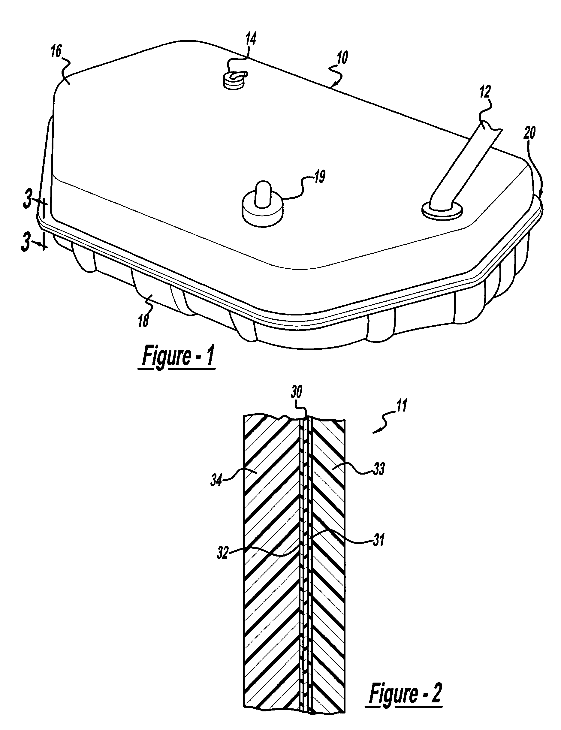
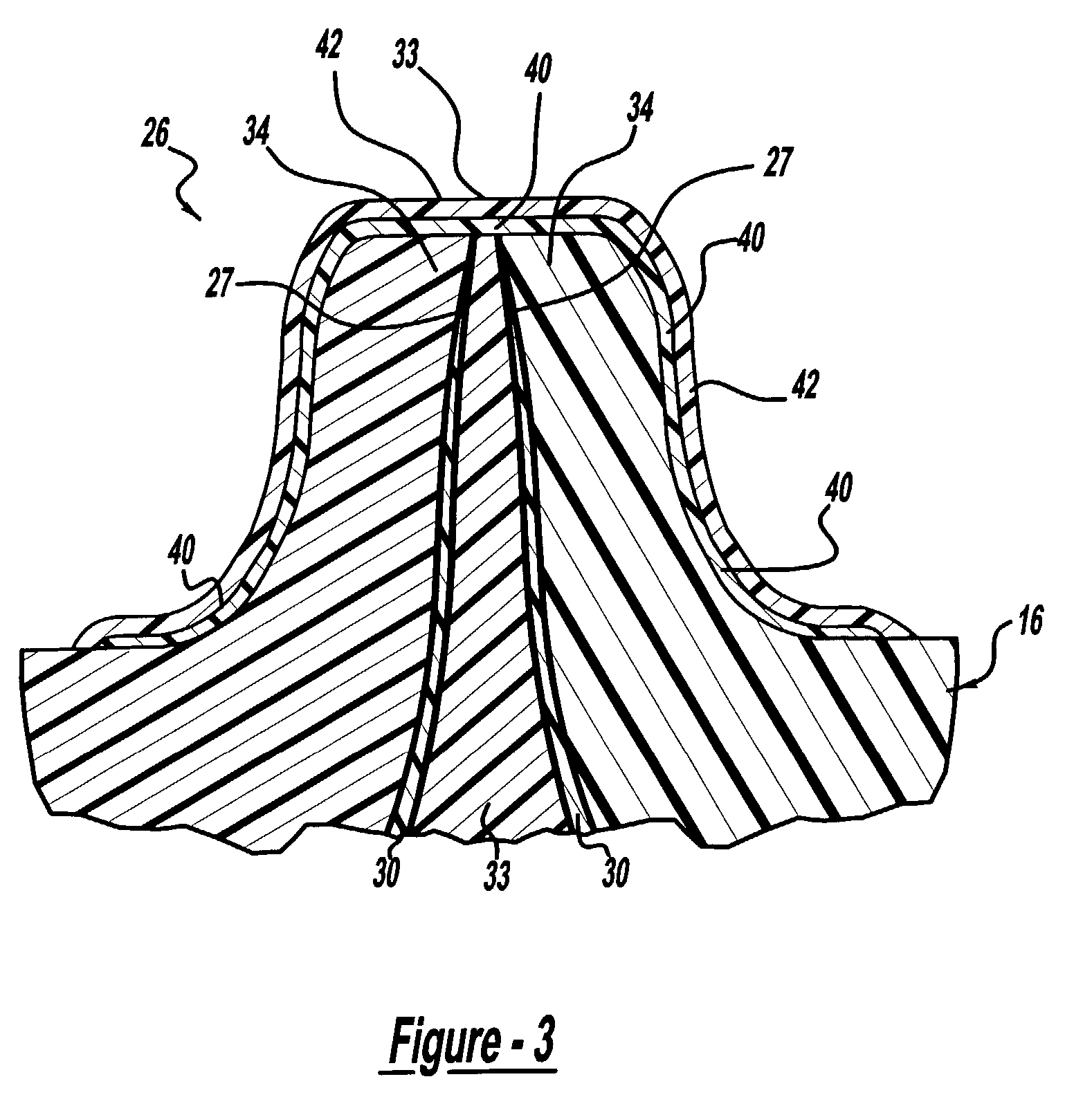
[0020]A polymeric fuel tank shell 10 is generally illustrated in FIG. 1 to include upper and lower shell halves 16 and 18 coupled together by flanges 20. The upper shell half 16 may include a filler neck or pipe 12, a vapor valve 14, a fill limit valve 19, and other attached items. The configuration of the filler neck 12, vapor valve 14, and fill limit valve 19 may vary from application to application.

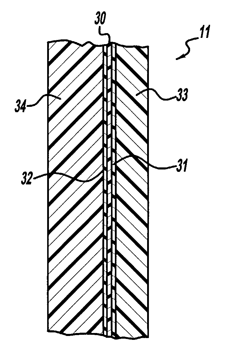
[0021]As shown in FIG. 2, the shell halves of fuel tank 10 are formed from a multilayer wall 11 having layers that provide structural support and a vapor barrier. Structural support layers 33 and 34 protect the fuel tank from abrasion and impact and provide the necessary rigidity and strength. The structural support layers 33 and 34 may be formed out of a variety of suitable materials known in the art such as polyethylene, high-density polyethylene, nylon, polypropylene, polyester, and a variety of other synthetic materials. Desirable properties of the structural s...


PUM

PropertyMeasurementUnit
temperaturesaaaaaaaaaa

Abstract

A permeation resistant polymer fuel tank having a multilayer wall that includes a structural layer and a vapor barrier layer. A secondary barrier layer is attached to the multilayer wall wherein the vapor barrier layer and the second barrier layer have a permeation rate less than the structural layer. A protective coating may be applied over the secondary barrier layer to add durability and prevent degradation of the secondary barrier layer from environmental hazards that fuel tanks may be exposed to.

Description

CROSS-REFERENCE TO RELATED APPLICATION[0001]This application claims the benefit of U.S. Provisional Application No. 60 / 395,008, filed Jul. 11, 2002, the entire disclosure of this application being considered part of the disclosure of this application and hereby incorporated by reference.BACKGROUND OF THE INVENTION[0002]The present invention relates to fuel tanks and more particularly to polymer fuel tanks, and a method for reducing permeation of gaseous fluids.[0003]Historically, fuel tanks have been manufactured from stamped metal shell halves. Metal fuel tanks are not only expensive, but add weight to a vehicle and are subject to corrosion. To reduce cost, weight, and avoid corrosion problems associated with metal fuel tanks, manufacturers have switched to using polymer fuel tanks in vehicles.[0004]Polymer or plastic fuel tanks are corrosion resistant and weigh less than metal fuel tanks. One problem with polymer fuel tanks is that fuel vapor may permeate through the polymeric con...

Claims


Application Information

Patent Timeline
Patent Type & Authority Patents(United States)
IPC IPC(8): B29D22/00B29D23/00B32B1/08B29C65/00B29C65/02B60K15/03
CPCB60K15/03177B29C65/02B29C66/038B29C66/13B29C66/53246B29C66/54B29C65/00B29L2031/7172Y10T428/1379B60K2015/03453Y10T428/1383B29K2995/0067B29L2009/00Y10T428/1352B29C66/112B29C66/131B29C66/1312B29C66/24221B29C66/71B29C66/712B29C66/72341B29C66/73793Y10T428/3158B29K2077/00B29K2075/00B29K2067/00B29K2027/08B29K2023/12B29K2023/086B29K2023/065B29K2023/06
Inventor POTTER, JAMES F.KNECHTGES, HEATHER L.
Owner VISTEON GLOBAL TECH INC
Learn More