
Coupling for joining two pipes

a technology of coupling and pipe, applied in the direction of couplings, pipe joints, flanged joints, etc., can solve the problems of joint loosening, inability to withstand the high temperature of fluid or pipes, and in the vicinity of a very hot object, so as to facilitate the opening of the coupling, increase the protection against the spread of the rings, and facilitate the effect of coupling opening

Inactive Publication Date: 2006-07-13
NORMA GERMANY GMBH
View PDF13 Cites 19 Cited by
  • Summary
  • Abstract
  • Description
  • Claims
  • Application Information

AI Technical Summary

Benefits of technology

[0023] Alternatively, each ring can have been produced as a closed ring by injection molding. This eliminates their production from strips, bending them together in the shape of a ring, and joining the ends of the strips.
[0035] In addition, the webs can be held together by a connecting device, which releasably bridges the ring break or each ring break. This connecting device increases protection against spreading of the rings under high bending forces exerted on the coupling. At the same time, it serves as an assembly indicator, which makes it evident whether the connection of the pipes by the coupling has been carried out correctly.

Problems solved by technology

However, if a very hot fluid is to be conducted through the pipes that are to be joined, it is possible that at least those parts of the coupling that come into direct contact with the pipes will not be able to withstand the high temperatures of the fluid or the pipes.
The same problem can occur in the vicinity of a very hot object, e.g., the engine or exhaust system of a motor vehicle.
Therefore, the coupling is unable to withstand strong forces that act to bend the pipes relative to each other, so that the joint would become loose.

Method used


Image

  • Coupling for joining two pipes
  • Coupling for joining two pipes
  • Coupling for joining two pipes

Examples


Embodiment Construction

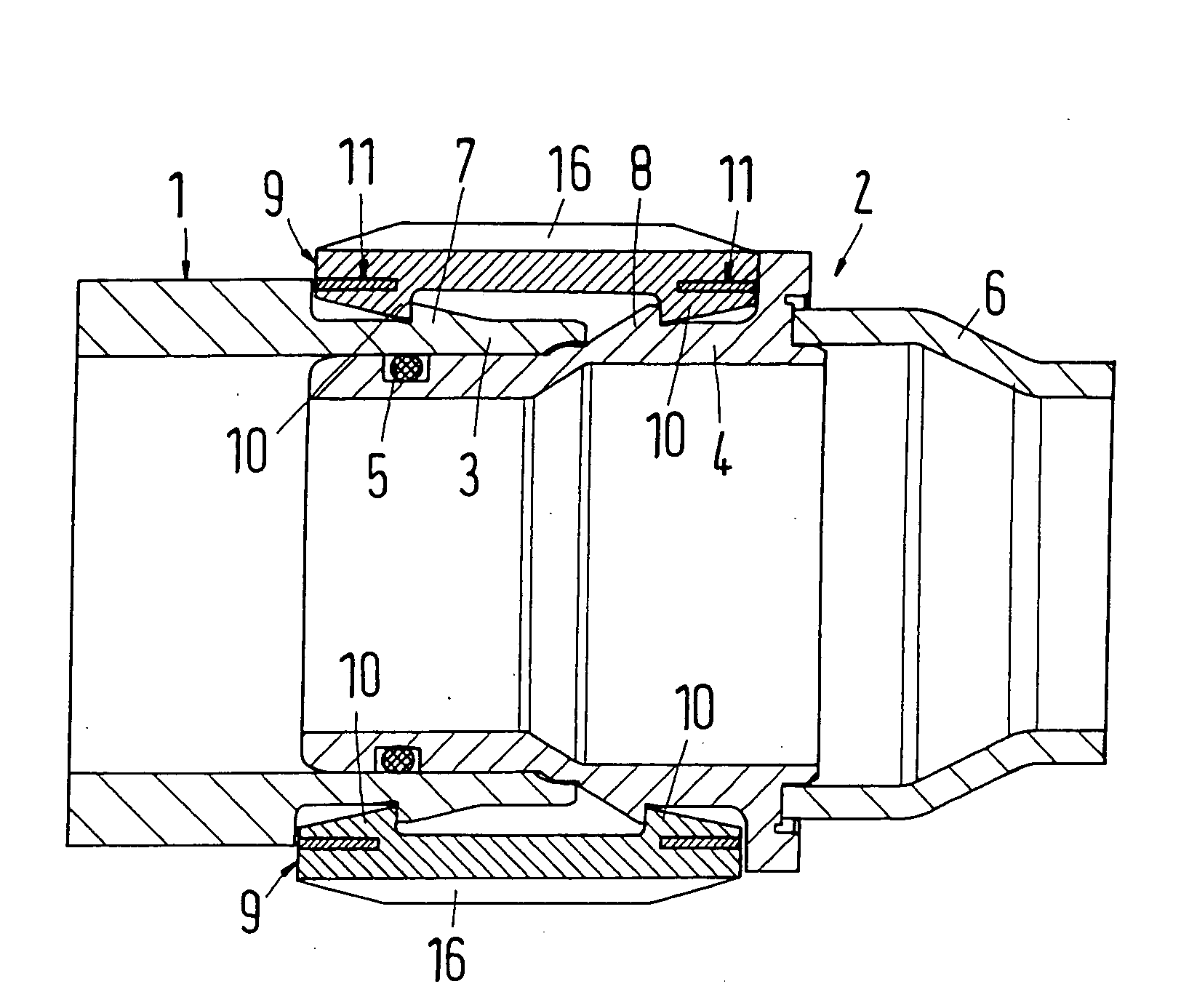
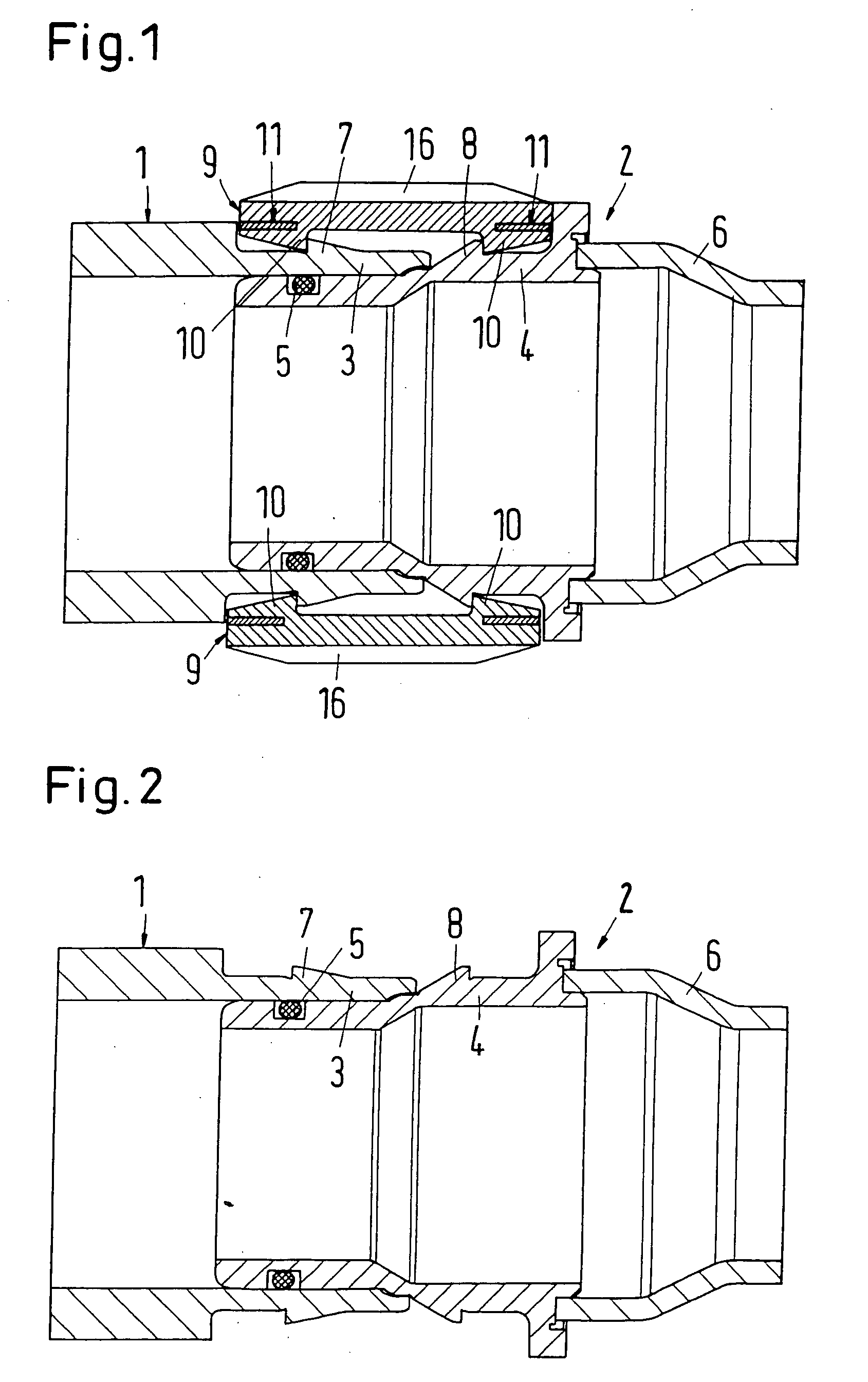
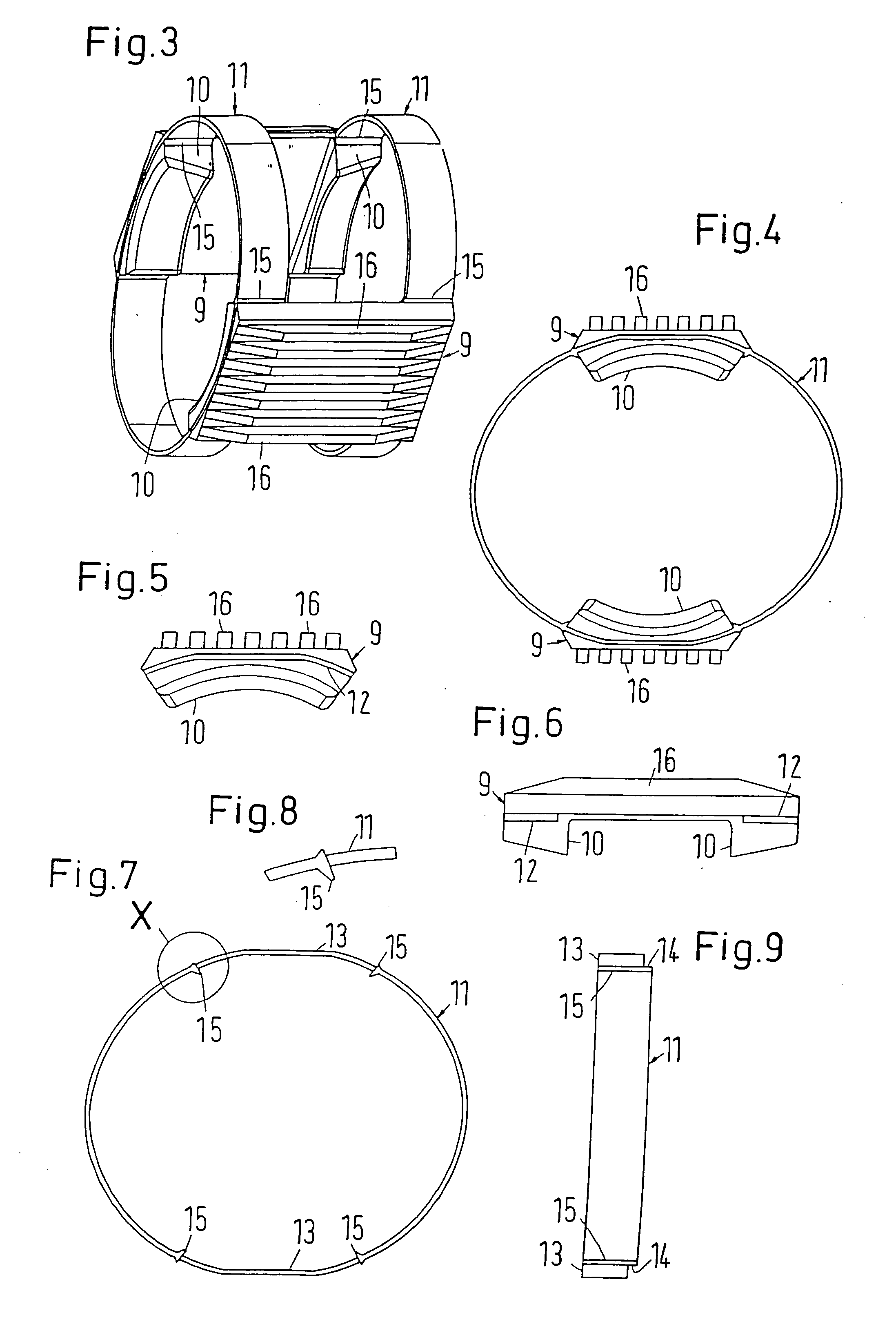
[0061]FIG. 1 and FIGS. 3 to 9 show a specific embodiment of the coupling of the invention and its individual parts. The coupling is used to join two pipes 1 and 2, which are made of a thermoplastic material or metal and are only partially shown in the drawings. Pipes 1 and 2 are shown in FIG. 2 without the coupling. The end sections 3 and 4 of the pipes 1 and 2 are inserted in the coupling and fitted together. The regions of the end sections 3 and 4 that are fitted together are sealed from each other by a gasket 5. The end section 4 is welded to the remaining part 6 of the pipe 2. Each end section 3 and 4 has a circumferential locking rib 7 and 8, respectively.

[0062] The coupling has radially inwardly projecting stop projections 10 at the ends of axial, flexurally stiff webs 9. The stop projections lock or snap in behind the locking ribs 7 and 8 when the end sections 7 and 8 are inserted in the coupling, and at the same time they fit together. For this purpose, the webs 9 are joine...


PUM


Abstract

Coupling for joining two pipes, whose end sections, each of which is provided with a circumferential locking rib, can be inserted in the coupling, wherein the coupling has at least one elastic ring that joins at least two elongated webs, and wherein the coupling has stop projections, which lock in place behind the locking ribs when the end sections are inserted in the coupling and can be unlocked to release the connection of the pipes by expanding at least one of the rings. Each ring is produced separately from the webs.

Description

BACKGROUND OF THE INVENTION [0001] 1. Field of the Invention [0002] The present invention relates to a coupling for joining two pipes, whose end sections, each of which is provided with a circumferential locking rib, can be inserted into the coupling, wherein the coupling has at least one elastic ring that joins at least two elongated webs, and wherein the coupling has stop projections, which lock in place behind the locking ribs when the end sections are inserted in the coupling and can be unlocked to release the connection of the pipes by expanding at least one of the rings. [0003] 2. Description of the Related Art [0004] A coupling of this type is known from EP 1 378 701 A1. It is produced as a one-piece injection-molded plastic part. However, if a very hot fluid is to be conducted through the pipes that are to be joined, it is possible that at least those parts of the coupling that come into direct contact with the pipes will not be able to withstand the high temperatures of the...

Claims


Application Information

Patent Timeline
Patent Type & Authority Applications(United States)
IPC IPC(8): F16L23/00
CPCF16L37/0842F16L37/0985F16L37/22F16L37/12
Inventor KERTESZ, JANOSWACHTER, GERHARD
Owner NORMA GERMANY GMBH
Learn More