Detector circuit to be used for measuring current

a current measurement and current technology, applied in the field of current measurement circuits, can solve the problems of destroying effect, unable to compensate for alternating current, and inability of the magnetic integrator to handle dc and very low frequencies, so as to reduce parasitic capacity, undesirable capacitive current between the windings is significantly reduced, and parasitic capacity is reduced

Inactive Publication Date: 2006-07-13
LIAISONS ELECTRONIQUES MECANIQUES LEM
View PDF5 Cites 2 Cited by
  • Summary
  • Abstract
  • Description
  • Claims
  • Application Information

AI Technical Summary

Benefits of technology

[0007] The invention is based on the recognition that the undesirable resonances are caused by parasitic capacities in the common winding surrounding at least two annular cores, and according to the invention these parasitic capacities may be highly reduced by the winding for the compensating current being wound in such a manner that said parasitic capacities are reduced to a minimum, for instance by said winding being a so-called “pilgrim winding”. A pilgrim-wound transformer resulting from one section being wound at a time presents the property that the potential difference between the individual winding layers is smaller than in connection with conventionally wound transformers where one layer is wound at a time in the longitudinal direction of the entire core. As a result the undesirable capacitive currents between the windings have been significantly reduced. In other words, the parasitic capacities are reduced. In addition it turned out that the use of such a winding implies that the undesirable resonances are elevated to such an extent that they no longer interfere with the measuring procedure.

Problems solved by technology

However, the magnetic integrator cannot handle DC and very low frequencies, and accordingly it is necessary to include a separate circuit for this function.
An unbalance between the ampere winding numbers results in a voltage of an amplitude and a polarity which depend on the extent and polarity of said unbalance.
However, the known circuits are encumbered with the draw-back that it is not possible to compensate for alternating currents of a particularly high frequency.
In addition, undesirable resonances are generated which can have a destroying effect.

Method used


Image

  • Detector circuit to be used for measuring current
  • Detector circuit to be used for measuring current
  • Detector circuit to be used for measuring current

Examples


Embodiment Construction

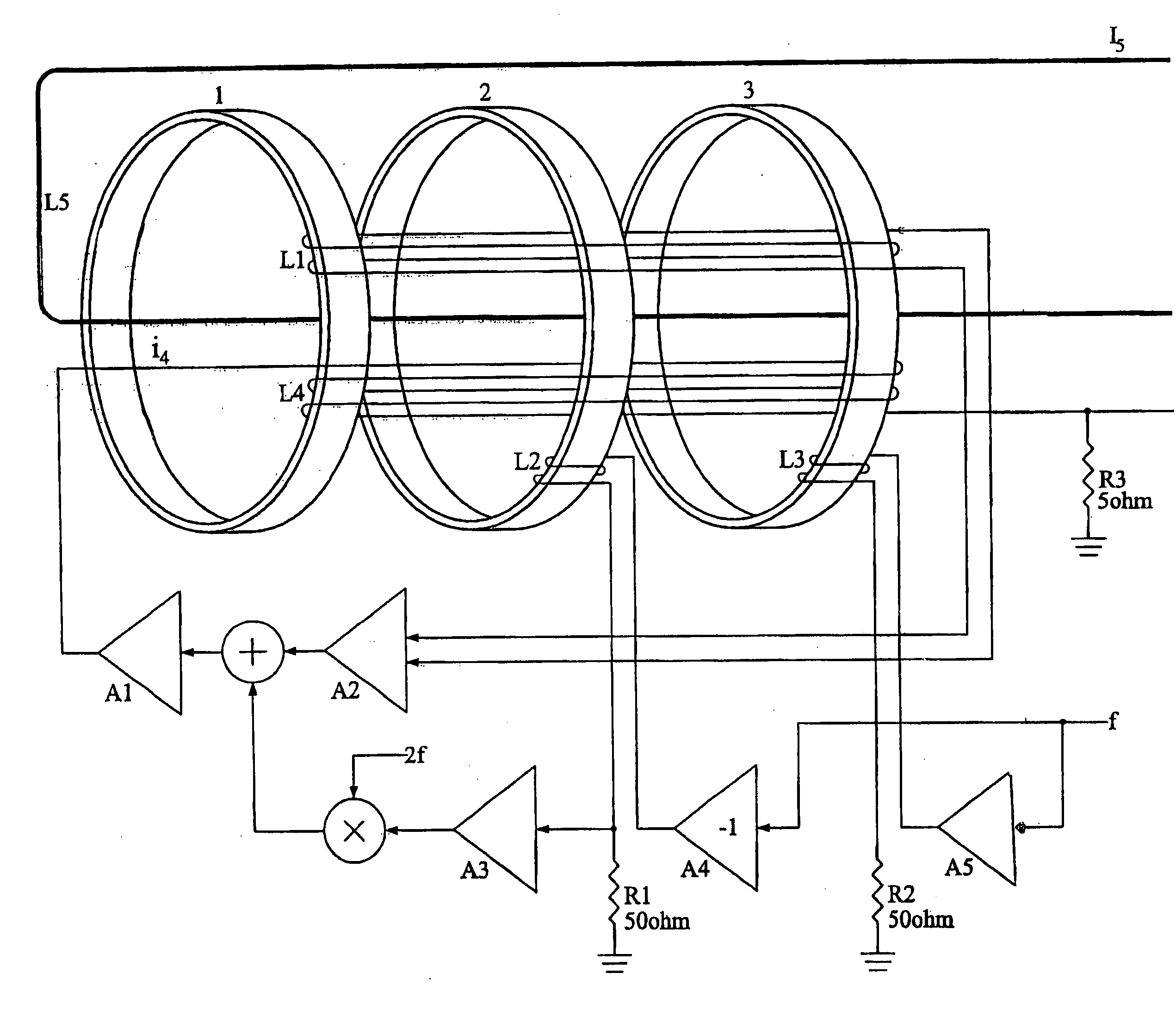
[0016] The detector circuit shown in FIG. 1 is to be used for measuring strong currents, and it includes three substantially identical annular cores 1, 2, 3. A main current I5 runs through the three substantially identical annular cores and induces magnetomotive forces which are to be counteracted by a compensating current i4. A modulation signal in form of a square wave signal of a frequency of a few hundred Hz is fed to the windings L2, L3 of two of these cores 2, 3, the square wave signal fed to the winding L2 of one core 2 being inverted relative to the square wave signal fed to the winding L3 of the second core 3. As a result, the two cores 2, 3 are magnetized in antiphase in such a manner that both the unequal and the equal harmonics are substantially compensated for through a coupling via the windings L1, L4 and L5.

[0017] The principle is based on the fact that the average flux in the cores is zero when equilibrium or a balance exists between the fields induced by the main c...


PUM


Abstract

A detector circuit to be used for measuring current and including a main current transformer and two substantially identical auxiliary current transformers, where magnetomotive forces are induced by a main current, said magnetomotive forces being counteracted by magnetomotive forces induced by a compensating current (i4) in a compensating winding (L4) across at least two annular cores (2, 3) at the same time as the two auxiliary current transformers are magnetized in antiphase by means of a modulation signal, said circuit further including a synchronous rectifier for providing an adjustment signal for the compensating current (i4). According to the invention, the compensating winding (L4) is formed by a so-called “pilgrim winding”. A pilgrim winding results from one section being wound at a time, and it presents the property that the potential difference between the individual winding layers is smaller than in connection with conventionally wound transformers where one layer is wound at a time in the longitudinal direction of the entire core. As a result the undesirable capacitive currents between the windings have been significantly reduced, viz. the so-called neighbouring effect. In other words, the parasitic capacities between the windings have been reduced. In addition it turned out that the use of such windings implies that the undesirable resonances are elevated to such an extent that they no longer interfere with the measuring procedure.

Description

TECHNICAL FIELD [0001] The invention relates to a detector circuit to be used for measuring current by means of a main current transformer and two substantially identical auxiliary transformers, where magnetomotive forces are induced by a main current, said magnetomotive forces being counteracted by magnetomotive forces induced by a compensating current in a winding surrounding at least two annular cores at the same time as the two auxiliary transformers are magnetized in antiphase by means of a modulation signal, said circuit including a synchronous rectifier for providing an adjustment signal for the compensating current. BACKGROUND ART [0002] Danish Patent No. 149238 discloses a zero-flux current transformer for measuring the current for an electromagnet in a particle accelerator. As very heavy current intensities are involved, viz. several hundred amperes, the main current is advantageously converted into a comparatively weaker measuring current which is easy to handle, and whic...

Claims


Application Information

Patent Timeline
Patent Type & Authority Applications(United States)
IPC IPC(8): H02P7/06H02K21/00H02K31/00
CPCG01R15/185G01R19/20
Inventor PETERSEN, JAN RAAGAARD
Owner LIAISONS ELECTRONIQUES MECANIQUES LEM
Why Eureka
Try Eureka