EMI filter employing a self-resonant inductor bandstop filter having optimum inductance and capacitance values

a self-resonant inductor and filter technology, applied in the field of new emi tank filter assemblies, can solve the problem of very high impedance and achieve the effect of rapid imagery

Inactive Publication Date: 2014-08-28
WILSON GREATBATCH LTD
View PDF6 Cites 2 Cited by
  • Summary
  • Abstract
  • Description
  • Claims
  • Application Information

AI Technical Summary

Benefits of technology

[0020]The present invention comprises resonant tank circuits / bandstop filters to be placed at one or more locations along the active implantable medical device (AIMD) lead system, including its distal Tip. These bandstop filters prevent current from circulating at selected frequencies of the medical therapeutic device. For example, for an MRI system operating at 1.5 Tesla, the pulse RF frequency is 64 MHz. The novel bandstop filters of the present invention can be designed to resonate at 64 MHz and thus create an open circuit in the implanted lead system at that selected frequency. For example, the bandstop filter of the present invention, when placed at the distal TIP, will prevent currents from flowing through the distal TIP, prevent currents from flowing in the implanted leads and also prevent currents from flowing into body tissue. It will be obvious to those skilled in the art that all of the embodiments described herein are equally applicable to a wide range of other active implantable medical devices, including deep brain stimulators, spinal cord stimulators, cochlear implants, ventricular assist devices, artificial hearts, drug pumps, and the like. The present invention fulfills all of the needs regarding reduction or elimination of undesirable currents and associated heating in implanted lead systems.
[0026]In the preferred embodiment, the overall Q factor of the bandstop filter is selected to balance impedance at the selected frequency versus frequency band width characteristics. More specifically, the Q of the inductor is relatively maximized and the Q of the capacitor is relatively minimized to reduce the overall Q of the bandstop filter. The Q of the inductor is relatively maximized by minimizing the parasitic resistive loss in the inductor, and the Q of the capacitor is relatively minimized by raising its equivalent series resistance (ESR) of the capacitor (or by adding resistance or a resistive element in series with the capacitor element of the bank stop tank filter). This reduces the overall Q of the bandstop filter in order to broaden its 3 dB points and thereby attenuate current flow through the lead along a range of selected frequencies. In AIMD or external medical device applications, the range of selected frequencies includes a plurality of MRI pulsed frequencies.
[0027]The equivalent series resistance of the capacitor is raised by any of the following: reducing thickness of electrode plates in the capacitor; using higher resistivity capacitor electrode materials, providing apertures, gaps, slits or spokes in the electrode plates of the capacitor; providing separate discrete resistors in series with the capacitor; utilizing resistive electrical attachment materials to the capacitor; or utilizing capacitor dielectric materials that have high dielectric loss tangents at the selected frequency. Methods of using higher resistivity capacitor electrode materials include, for example, using platinum instead of silver electrodes. Platinum has a higher volume resistivity as compared to pure silver. Another way of reducing capacitor electrode plate resistivity is to add ceramic powders to the electrode ink before it is silk screened down and fired. After firing, this has the effect of separating the conductive electrode portions by insulative dielectric areas which increases the overall resistivity of the electrode plate.
[0028]As defined herein, raising the capacitor ESR includes any or all of the above described methods of adding resistance in series with the capacitive element of the bandstop filter. It should be noted that deliberately raising the capacitor ESR runs counter to conventional / prior art capacitor technologies. In fact, capacitor manufacturers generally strive to build capacitors with as low an ESR as possible. This is to minimize energy loss, etc. It is a feature of the present invention that capacitor Q is raised in a controlled manner in the tank filter circuit in order to adjust its Q and adjust the bandstop frequency width in the range of MRI pulsed frequencies.
[0031]The overall Q of the tank filter circuit may be reduced by increasing the Q of the inductor and reducing the Q of the capacitor. In this regard, minimizing resistive loss in the inductor maximizes the Q of the inductor, and raising the equivalent series resistance of the capacitor minimizes the Q of the capacitor.
[0032]The net effect is to reduce the overall Q of the tank filter circuit which widens the bandstop width to attenuate current flow through the lead along a range of selected frequencies. As discussed herein, the range of selected frequencies may include a plurality of MRI pulse frequencies.

Problems solved by technology

It is also well known that when the tank filter is at its resonant frequency, it will present a very high impedance.

Method used


Image

  • EMI filter employing a self-resonant inductor bandstop filter having optimum inductance and capacitance values
  • EMI filter employing a self-resonant inductor bandstop filter having optimum inductance and capacitance values
  • EMI filter employing a self-resonant inductor bandstop filter having optimum inductance and capacitance values

Examples


Embodiment Construction

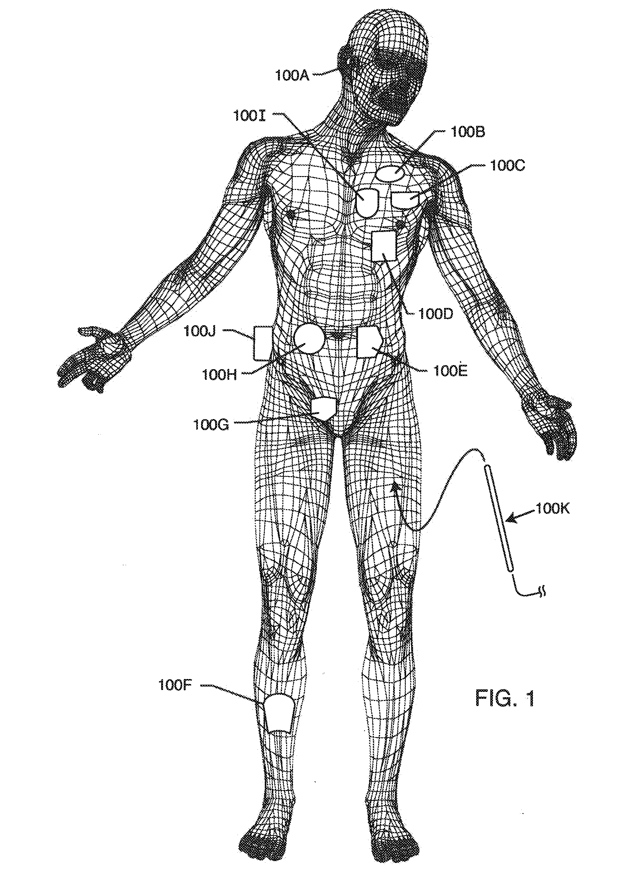
[0062]FIG. 1 illustrates of various types of active implantable medical devices 100 that are currently in use. FIG. 1 is a wire formed diagram of a generic human body showing a number of implanted medical devices. 100A is a family of implantable hearing devices which can include the group of cochlear implants, piezoelectric sound bridge transducers and the like. 100B includes an entire variety of neurostimulators and brain stimulators. Neurostimulators are used to stimulate the Vagus nerve, for example, to treat epilepsy, obesity and depression. Brain stimulators are similar to a pacemaker-like device and include electrodes implanted deep into the brain for sensing the onset of the seizure and also providing electrical stimulation to brain tissue to prevent the seizure from actually happening. 100C shows a cardiac pacemaker which is well-known in the art. 100D includes the family of left ventricular assist devices (LVAD's), and artificial hearts, including the recently introduced ar...


PUM


Abstract

A bandstop filter having optimum component values is provided for a lead of an active implantable medical device (AIMD). The bandstop filter includes a capacitor in parallel with an inductor. The parallel capacitor and inductor are placed in series with the implantable lead of the AIMD, wherein values of capacitance and inductance are selected such that the bandstop filter is resonant at a selected frequency. The Q of the inductor may be relatively maximized and the Q of the capacitor may be relatively minimized to reduce the overall Q of the bandstop filter to attenuate current flow through the implantable lead along a range of selected frequencies.

Description

CROSS-REFERENCE TO RELATED APPLICATIONS[0001]This application is a continuation of U.S. patent application Ser. No. 12 / 707,084, filed on Feb. 17, 2010, which is a continuation-in-part of U.S. application Ser. No. 11 / 423,073, filed Jun. 8, 2006.BACKGROUND OF THE INVENTION[0002]This invention relates generally to novel EMI tank filter assemblies, particularly of the type used in connection with active implantable medical devices (AIMDs) such as cardiac pacemakers, cardioverter defibrillators, neurostimulators, and the like, which decouple implantable leads and / or electronic components of the implantable medical device from undesirable electromagnetic interference (EMI) signals at a selected frequency or frequencies, such as the RF pulsed fields of Magnetic Resonance Imaging (MRI) equipment.[0003]Compatibility of cardiac pacemakers, implantable defibrillators and other types of active implantable medical devices with magnetic resonance imaging (MRI) and other types of hospital diagnost...

Claims


Application Information

Patent Timeline
Patent Type & Authority Applications(United States)
IPC IPC(8): H03H1/00
CPCH03H1/00H03H2001/0092A61N1/05A61N1/37A61N1/3718A61N1/086G01R33/285G01R33/288H03H1/0007H03H7/0115H03H7/1766H03H2007/013
Inventor STEVENSON, ROBERT A.DABNEY, WARREN S.JOHNSON, ROBERT SHAWNMOSCHIANO, HOLLY NOELLEHALPERIN, HENRY R.
Owner WILSON GREATBATCH LTD
Why Eureka
Try Eureka