Electromechanical transducer device and method of making the same

a transducer and electromechanical technology, applied in the direction of electrical transducers, mechanical vibration separation, influence generators, etc., can solve the problems of limited number of cavities that can be formed per unit area of substrates, inability to form cavities, and difficulty in supporting cavities, etc., to achieve sufficient width, reduce parasitic capacity, and high density

Inactive Publication Date: 2015-09-22
CANON KK
View PDF15 Cites 0 Cited by
  • Summary
  • Abstract
  • Description
  • Claims
  • Application Information

AI Technical Summary

Benefits of technology

[0009]According to the present invention, by making the width of the groove on the first surface side of the substrate smaller than the width of the groove on the second surface side, a plurality of electromechanical transducer elements can be disposed with a comparatively high density on the first surface side. By making the width of the groove become larger from the first surface side toward the second surface side, a sufficient width is provided to the separation groove as a whole. Therefore, electrical isolation between electromechanical transducer elements can be secured and the parasitic capacity can be reduced. As a result, decrease in sensitivity, which occurs due to a small width of the groove on the first surface side, can be suppressed. Moreover, because the width of the groove on the first surface side can be reduced while suppressing decrease in sensitivity, electromechanical transducer elements can be disposed with a high density, whereby the fill factor can be increased. Also in this respect, the sensitivity of the electromechanical transducer device, such as a CMUT, can be increased. In other words, according to the present invention, the parasitic capacity between electromechanical transducer elements can be reduced while increasing the signal output of the electromechanical transducer device.

Problems solved by technology

However, cavities cannot be formed in a region that corresponds to the separation groove (directly above the separation groove) and for which it is difficult to support a cavity.
Therefore, the number of cavities that can be formed per unit area of a substrate is limited.

Method used


Image

  • Electromechanical transducer device and method of making the same
  • Electromechanical transducer device and method of making the same
  • Electromechanical transducer device and method of making the same

Examples


first embodiment

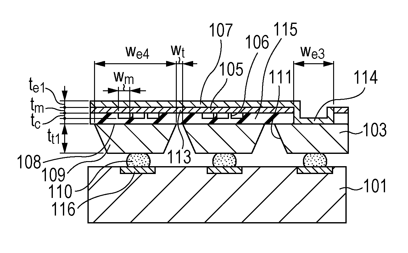
[0022]Referring to FIGS. 1A to 1C, a first embodiment will be described. The first embodiment is a capacitance-type ultrasonic transducer device that includes a silicon substrate in which elements are separated by grooves and a membrane 105 is made by joining a silicon-on-insulator (SOI) substrate to the silicon substrate. FIG. 1A is a sectional view of an electromechanical transducer device 100 according to the first embodiment. As illustrated in FIG. 1A, the electromechanical transducer device 100 includes a circuit board 101 and a silicon substrate 103. The circuit board 101 is disposed directly below the silicon substrate 103.

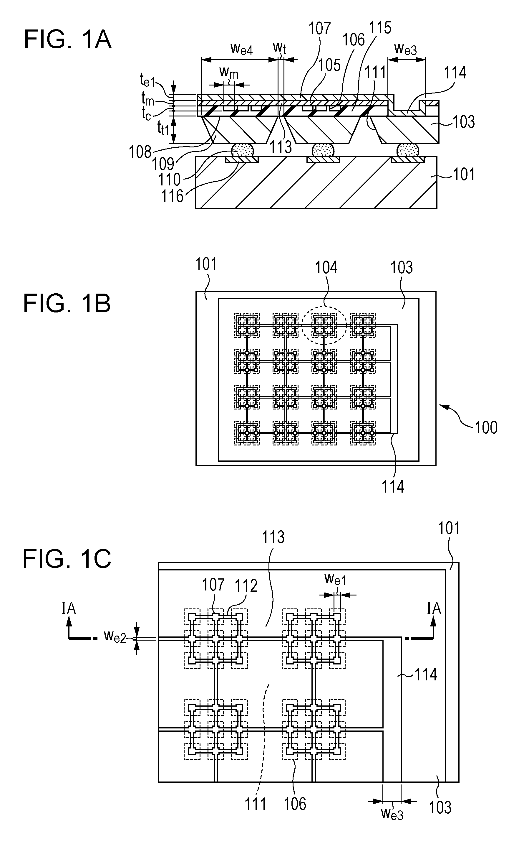
[0023]FIG. 1B is a top view of FIG. 1A. As illustrated in FIG. 1B, the electromechanical transducer device 100 according to the first embodiment includes 4×4 elements 104. A region surrounded by a dotted line in FIG. 1B corresponds to one of the elements 104. Each of the elements 104, which is a capacitance-type electromechanical transducer element, individ...

second embodiment

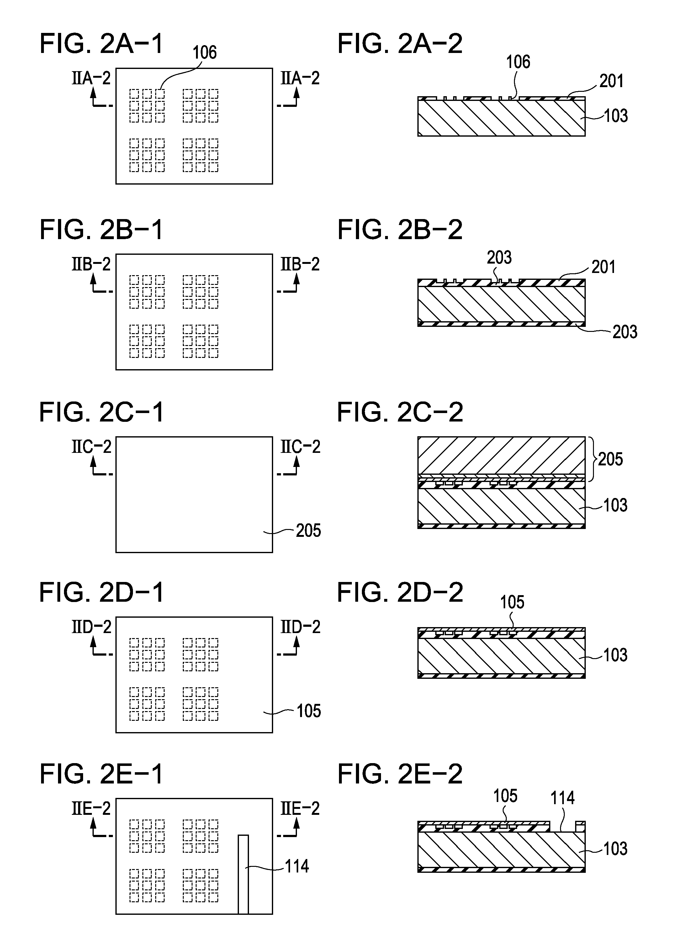
[0029]A second embodiment will be described. The embodiment relates to a method of making the CMUT described in the first embodiment. FIGS. 2A-1 to 2I-2 illustrate a method of making a CMUT according to a second embodiment of the present invention. For convenience of illustration, sectional views of two elements are illustrated in FIGS. 2A-1 to 2I-2. Other elements can be made in the similar manner. In FIGS. 2A-1 to 2I-2, portions of the CMUT that function in the similar manner as those illustrated in FIGS. 1A to 1C are denoted by the same numerals.

[0030]First, the silicon substrate 103 is prepared. Typically, the silicon substrate 103 is a single crystal silicon, to which semiconductor processing techniques can be easily applied. The silicon substrate 103 may have a low resistivity (i.e., a certain degree of conductivity), because the silicon substrate 103 becomes the lower electrode 108 and the through-hole interconnection 109. In the second embodiment, an Si substrate having a re...

third embodiment

[0040]Referring to FIG. 3A, a third embodiment will be described. The third embodiment is a CMUT that is basically the same as that of the first embodiment, but differs from the first embodiment in that the groove 111 has a cross-sectional shape that is step-like. The groove 111 is characterized in that the groove 111 has a small width at a portion that is close to the element 104. By providing the groove 111 with such a cross-sectional shape, a larger number of cavities can be disposed while minimizing an increase in the parasitic capacity generated between the elements 104 that are adjacent to each other. FIG. 3B illustrates the groove 111 that has a larger width at a position that is away from the element 104. Although the number of cavities that can be disposed is the same as the case of FIG. 3A, the parasitic capacity between the adjacent element 104 increases, and the noise increases. The larger the average width of the groove in the depth direction, the smaller becomes the pa...


PUM

PropertyMeasurementUnit
widthaaaaaaaaaa
width wmaaaaaaaaaa
width wmaaaaaaaaaa

Abstract

Provided is an electromechanical transducer device including a substrate that is conductive, and a plurality of electromechanical transducer elements disposed on a first surface of the substrate. A groove that electrically isolates the plurality of electromechanical transducer elements from each other is formed in the substrate, the groove extending from a second surface side of the substrate toward the first surface side of the substrate, the second surface being opposite the first surface. The width of the groove on the first surface side of the substrate is smaller than the width of the groove on the second surface side of the substrate.

Description

BACKGROUND OF THE INVENTION[0001]1. Field of the Invention[0002]The present invention relates to an electromechanical transducer device, such as an ultrasonic transducer, and to a method of making the electromechanical transducer device.[0003]2. Description of the Related Art[0004]Ultrasonic transducers, which convert an electric signal into ultrasound and vice versa, are used as probes for medical imaging and non-destructive testing. There is a type of ultrasonic transducer called a capacitive micromachined ultrasound transducer (CMUT). A CMUT includes, for example, a substrate including a lower electrode, a membrane that is supported by a supporting unit formed on the substrate, and an upper electrode. The lower electrode, the membrane, the upper electrode, and the supporting unit surround a cavity. The CMUT emits a sound wave (oscillatory wave) when a voltage is applied between the lower electrode and the upper electrode and thereby the membrane is vibrated. On the other hand, a ...

Claims


Application Information

Patent Timeline
Patent Type & Authority Patents(United States)
IPC IPC(8): H02N1/08H04R31/00B06B1/02
CPCH04R31/00B06B1/0292H02N1/08Y10T29/49005
Inventor OGAWA, TOSHIYUKITAKAGI, MAKOTOKATO, KAZUHIKO
Owner CANON KK
Why Eureka
Try Eureka