Optical disk and optical disk manufacturing method and device

a manufacturing method and optical disk technology, applied in the field of optical disks, can solve the problems of air bubbles infiltrating the resin of the two substrates, the thickness of the resin is difficult to be uniform, so as to achieve the effect of reducing thickness errors

Inactive Publication Date: 2006-07-13
ORIGIN ELECTRIC CO LTD
View PDF5 Cites 9 Cited by
  • Summary
  • Abstract
  • Description
  • Claims
  • Application Information

AI Technical Summary

Benefits of technology

[0019] With this configuration, as the first resin and second resin consist of ultraviolet-curing resin, it is possible to easily conduct curing of the spread first resin and curing of the spread second resin in the surrounding vicinity of the aperture by irradiation with ultraviolet rays.
[0040] The optical disk provided with this configuration reduces errors in thickness in the adhesive layer and the like, and is well suited to the recording of high-density data and the like.

Problems solved by technology

In this process, the air bubbles that have infiltrated the resin of the two substrates are also spun off, but it is difficult to make film thickness uniform when high-speed rotation is conducted in order to remove the air bubbles.
However, in the technology disclosed in patent document 1, when resin is toroidally applied to the surrounding vicinity of the aperture formed in the central part of the substrate, and when high-speed rotation is conducted, there is a tendency for the resin to thin on the inner circumferential side of the substrate and to thicken at the periphery.
In addition, in the technology disclosed in patent document 2, as crimping is conducted without rotating the disk substrates, there is a problem that the air bubbles that have infiltrated the resin of the two substrates remain unaltered.
In addition, in the technology disclosed in patent document 3, as the surfaces of the disk substrates are entirely irradiated with ultraviolet rays, there is a problem that occurrence of thickness irregularities in the ultraviolet-curing resin due to high-speed rotation of the disk cannot be fully suppressed.
In addition, in the technology disclosed in patent document 4, as the spreading of the resin is conducted only once and the vicinity of the central aperture is cured while spreading by rotation, there is a problem that it is difficult to control the thickness of the film.

Method used


Image

  • Optical disk and optical disk manufacturing method and device
  • Optical disk and optical disk manufacturing method and device
  • Optical disk and optical disk manufacturing method and device

Examples


Embodiment Construction

[0066] Embodiments of the present invention are explained below with reference to drawings. In the various drawings, devices that are mutually identical or equivalent are given the same code number, and duplicative description is omitted.

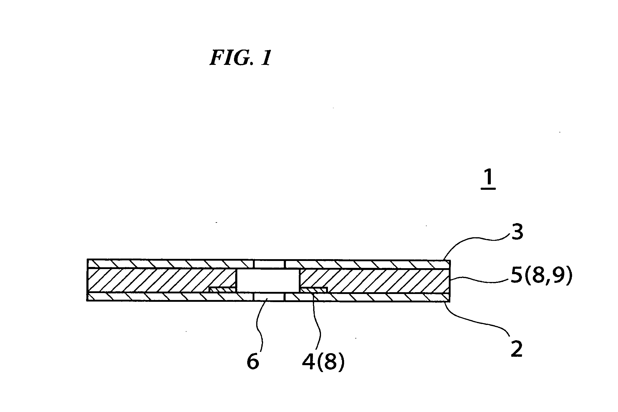
[0067] First, the configuration of the optical disk manufactured by the optical disk manufacturing method of the present invention is described with reference to FIG. 1. FIG. 1 is one example of a sectional view of an optical disk 1 manufactured by the below-described optical disk manufacturing method which is an embodiment of the present invention. The optical disk 1 is provided with the two disk substrates 2 and 3. The disk substrates 2 and 3 are typically disks made of polycarbonate resin, but the material is not limited to polycarbonate, and other materials that transmit laser beams may also be suitably used. The disk substrates 2 and 3 are thin plates, and a circular aperture 6 is formed in the center. The peripheral form is commonly circular,...


PUM

PropertyMeasurementUnit
thicknessaaaaaaaaaa
thicknessaaaaaaaaaa
diameteraaaaaaaaaa

Abstract

An optical disk manufacturing method including a process of toroidally supplying a first resin on one side of a first disk substrate having an aperture at the center, in a region adjacent to the perimeter of the aperture; a process of rotating the first disk substrate provided with the first resin at a first rotational speed, and spreading the first resin; a process of curing the spread first resin in the surrounding vicinity of the aperture; a process of toroidally supplying a second resin that is superimposed on the first resin of the first disk substrate on which the first resin has cured, in the region adjacent to the perimeter of the aperture; a process of rotating the first disk substrate provided with the second resin at a second rotational speed, and spreading the second resin; and a process of curing the spread second resin.

Description

BACKGROUND OF THE INVENTION [0001] 1. Field of the Invention [0002] The present invention relates to an optical disk and to a manufacturing method and a manufacturing apparatus of the optical disk. In particular, it relates to an optical disk where the thickness of the adhesive layer is uniform or where the thickness of the protective film is uniform when two disk substrates are joined together, and to the manufacturing method and manufacturing apparatus of the optical disk. [0003] Priority is claimed on Japanese Patent Application No. 2005-002349, filed Jan. 7, 2005, the content of which is incorporated herein by reference. [0004] 2. Description of Related Art [0005] Optical disks have evolved from CDs (compact disks) into DVDs (digital versatile disks) and further into next-generation DVDs, and their recording density has improved. With these optical disks, minute irregularities are formed in spiral grooves on the surface of, for example, a polycarbonate substrate, and the recorde...

Claims


Application Information

Patent Timeline
Patent Type & Authority Applications(United States)
IPC IPC(8): G11B7/24
CPCG11B7/266
Inventor KOBAYASHI, HIDEOSUZUKI, TAKAYUKINAKAMURA, MASAHIROOZAWA, NAOTO
Owner ORIGIN ELECTRIC CO LTD
Why Eureka
Try Eureka