Anchoring element for securing a rod of a device for adjusting a human or animal vertrebal column on a vertreba

a technology a rod is applied in the field of an anchoring element for fastening a rod of a device for adjusting a human or animal vertebra on a vertebra, which can solve the problems of reducing the size of the vertebra, reducing the size of the overall anchoring element, and reducing the size of the clamping surface. , the effect of reducing the force required for fixing the mount or the retaining means

Inactive Publication Date: 2006-07-13
METZ STAVENHAGEN PETER
View PDF10 Cites 363 Cited by
  • Summary
  • Abstract
  • Description
  • Claims
  • Application Information

AI Technical Summary

Benefits of technology

[0011] An anchoring element configured according to this technical teaching has the advantage that the mount and the retaining means are still movable with respect to the bearing and to the shaft and that the occurring forces are nevertheless positively transmitted thanks to the formed guiding surfaces and the mating counter surfaces. As compared to prior art, in this implementation the mount and the retaining means can only be moved in a direction transverse to the longitudinal axis. Therefore, the anchoring element of the invention could be called a uniaxial screw whereas the prior art anchoring element is termed a polyaxial screw since it is movable in any direction.
[0012] Another advantage of the anchoring element of the invention is that thanks to the positive force transmission the required clamping surface can be considerably reduced since it is no longer necessary to produce so strong a frictional connection. Therefore, the anchoring element of the invention can be implemented to be much smaller. This small anchoring element may then advantageously be implanted in the cervical vertebral region.
[0013] In a preferred embodiment, the guiding surfaces and / or the counter surfaces can be configured to be riffled or roughened. As a result thereof, the friction of the two surfaces against each other increases so that the forces required for fixing the mount or retaining means can be much smaller. Accordingly, this feature also contributes to reducing the size of the overall anchoring element since but a small surface is now needed to achieve sufficient clamping.
[0014] In another preferred embodiment a snap device is formed in the guiding surfaces and in the counter surfaces. Said snap device comprises, more specifically in the guiding surfaces and in the counter surfaces, radially disposed grooves that are spaced apart in such a manner that the counter surface engages into opposite grooves of the guiding surface and vice versa. During implementation, this registration fit of the two surfaces permits to already coarsely adjust the retaining means or the mount in the imposed snap steps prior to placing the rod. Prior to tightening the safety screw, fine adjustment is then of course still possible. This snap system facilitates implantation of the anchoring element and permits to further reduce its size since the retaining means or mount is already fixed by the snap system so that the actual clamping surface
[0015] In a further preferred embodiment, the bearing is configured to be roughened, at least in its region which is in the shape of a spherical segment and / or in the retaining surfaces of the intermediate element that are turned toward said region. By having the bearing thus roughened, the clamping of the mount on the bearing is improved so that the clamping effect is enhanced while the surface remains the same.

Problems solved by technology

When utilizing said anchoring elements on the ventral vertebral column, the forces that are to be transmitted from the rod onto the vertebral body may be very large so that the frictional connection provided is not capable of transmitting these large forces.
In such cases, the retaining means comes out of place and the rod is no longer in the desired position.

Method used


Image

  • Anchoring element for securing a rod of a device for adjusting a human or animal vertrebal column on a vertreba
  • Anchoring element for securing a rod of a device for adjusting a human or animal vertrebal column on a vertreba
  • Anchoring element for securing a rod of a device for adjusting a human or animal vertrebal column on a vertreba

Examples


Embodiment Construction

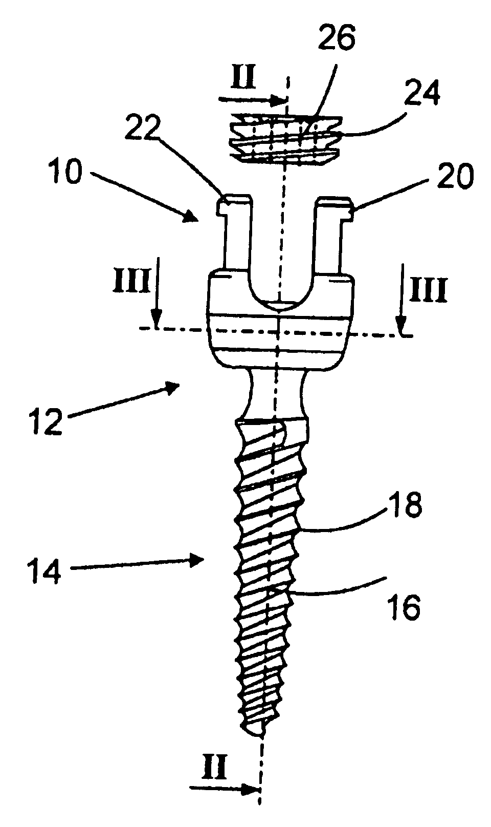
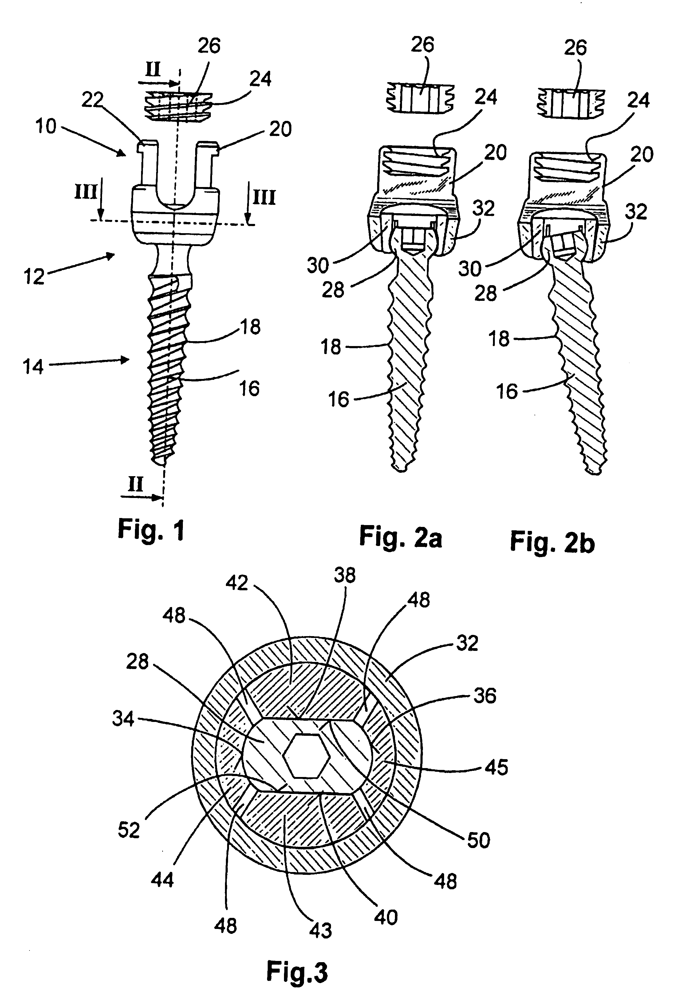
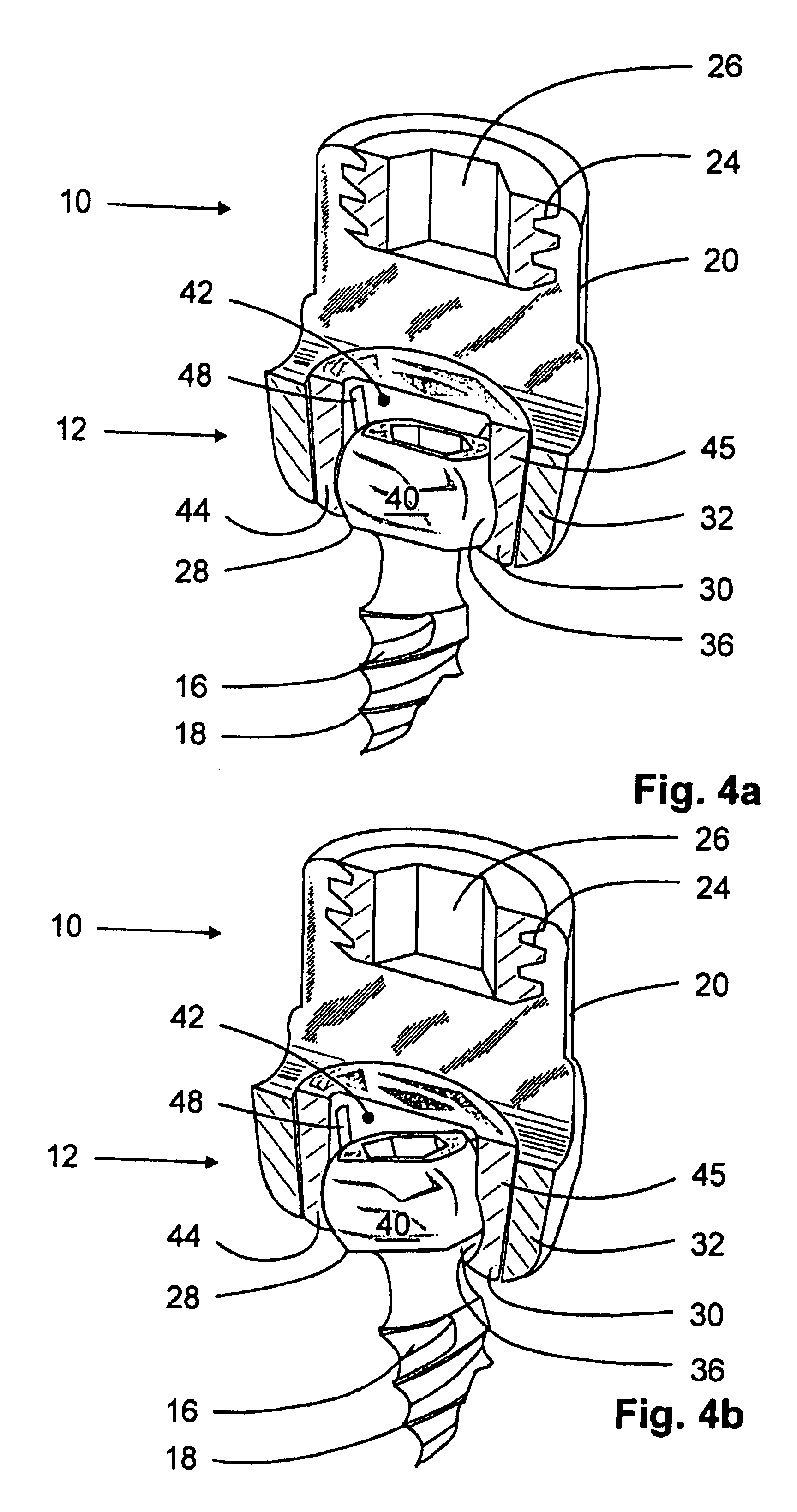
[0023] The anchoring element shown in the FIGS. 1 through 6 is a component part of a device for adjusting a human or animal vertebral column as it is sold for example by the trade name XIA available from Stryker Corp. This anchoring element serves to fasten a quite long rod on a vertebral bone and comprises a retaining means 10 for receiving a rod not shown herein, a clamping device 12 and a fastening element 14. The fastening element 14 is formed by a conically tapered shank 16 provided for example with a bio thread 18, a cancellous thread or the like. The anchoring element is inserted and fixed in the vertebral body by means of said fastening element 14.

[0024] The retaining means 10 is formed in a U-shaped configuration and comprises two coaxially arranged crosspieces 20, 22 provided, on their internal side, with a buttress thread 24. Said buttress thread 24 is described in detail in EP 0 885 598 A2. A securing element 26 configured as a grub screw may be screwed in axial directi...


PUM


Abstract

The invention relates to an anchoring element for securing a rod of a device for adjusting a human or animal vertebral column on a vertebra, comprising a retaining means (10) for receiving the rod, a safety element (26) placed on the retaining means and working against the rod, a securing element (14) which can be placed on the body of the vertebra, and a clamping device (12) which is arranged between the retaining means (10) and the securing element (14), comprising a ring-shaped mount (32), a partially conical-segment shaped bearing (28) and an intermediate element (30) which is embedded in the mount (32) and which engages the bearing, whereby the mounting (32) is moveable in a removed state in relation to the bearing (28), whereas the mount (32) is maintained in a clamped state on the bearing (28) by means of the intermediate element (30). The mount (32) is rigidly connected to the retaining means (10) and the bearing (28) is rigidly connected to the securing element (14). In order to enable said type of anchoring element, despite the fact that it is displaceably retained, to transmit relatively large amounts of force from the rod to the body of the vertebra without causing slipping, the bearing (28) comprises flat guiding surfaces (38, 40) which are formed laterally on two opposite sides (34, 36), and the intermediate element (30) is provided with corresponding counter surfaces (50, 52).

Description

CROSS-REFERENCE TO RELATED APPLICATION [0001] This application claims Priority from German Application No. DE 202 07 851.5 filed on 21 May 2002 BACKGROUND OF THE INVENTION [0002] 1. Field of the Invention [0003] The present invention relates to an anchoring element for fastening a rod of a device for adjusting a human or animal vertebral column on a vertebra, said anchoring element having a retaining means for receiving the rod, a securing element that is attachable on the retaining means and acting against the rod, a fastening element for attachment to the vertebral body and a clamping device which is arranged between the retaining means and the fastening element, including a ring-shaped mount, a bearing having partially the shape of a spherical segment and an intermediate element embedded in the mount and surrounding the bearing, the mount being free to move relative to the bearing when in its released state whilst the mount is clampingly retained on the bearing through the interm...

Claims


Application Information

Patent Timeline
Patent Type & Authority Applications(United States)
IPC IPC(8): A61F2/30A61B17/70
CPCA61B17/7032A61B17/7037A61B17/7038
Inventor METZ-STAVENHAGEN, PETER
Owner METZ STAVENHAGEN PETER
Why Eureka
Try Eureka