

Predictive action decision device and action decision method
a technology of action decision and action determination, applied in the field of prediction, can solve problems such as the difficulty of making a long-term state prediction, and achieve the effect of improving the accuracy and capability of action determination and improving the accuracy of action determination
- Summary
- Abstract
- Description
- Claims
- Application Information
AI Technical Summary
Benefits of technology
Problems solved by technology
Method used
Image

Examples
first embodiment
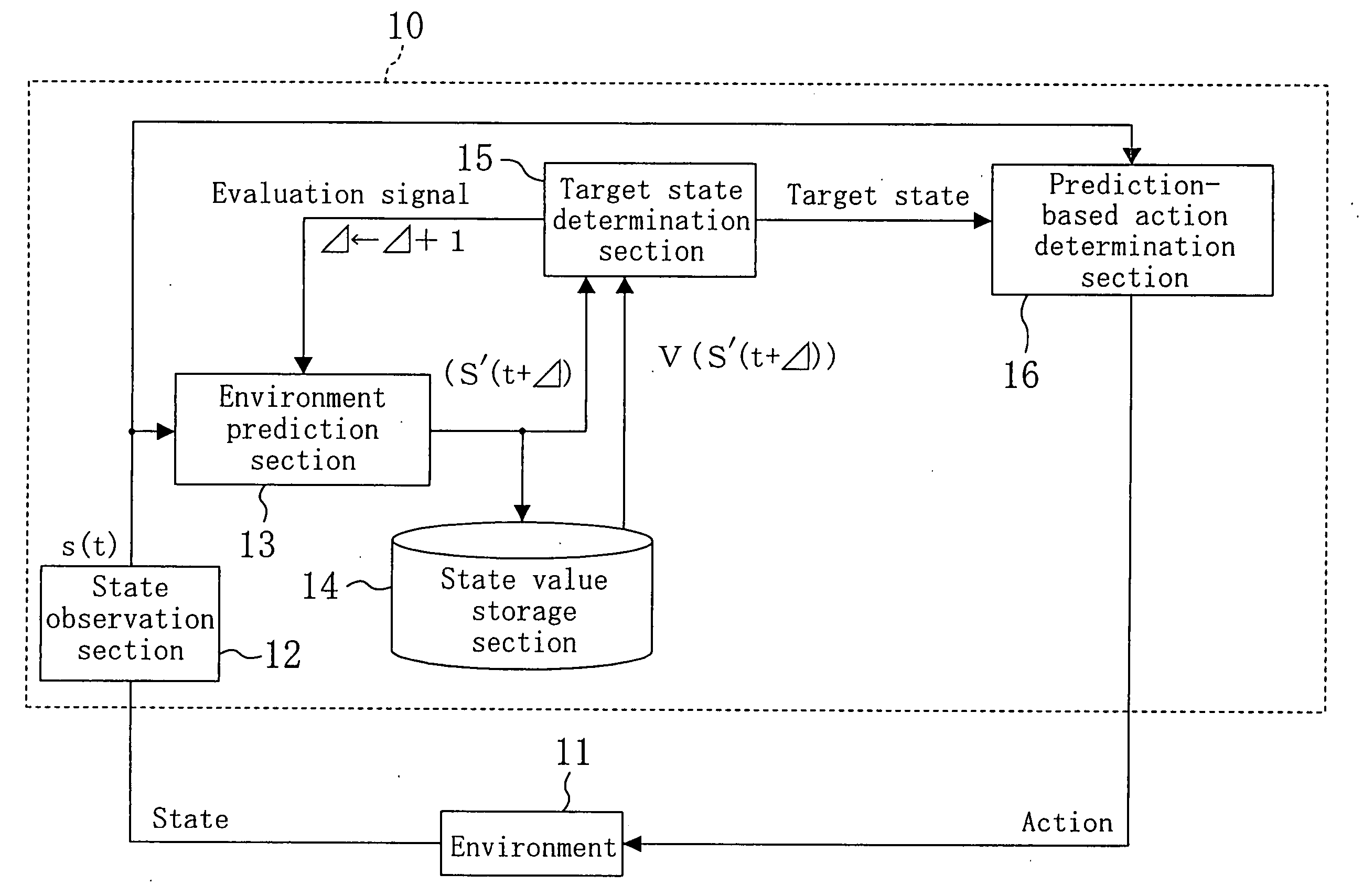
[0064]FIG. 4 is a block diagram illustrating a predictive action determination apparatus 10 according to a first embodiment of the present invention. The predictive action determination apparatus 10 observes a state with respect to a predetermined environment 11, predicts a state change with respect to the environment 11, which is not influenced by a self-action, sets a target state and then determines an action with respect to the environment 11.
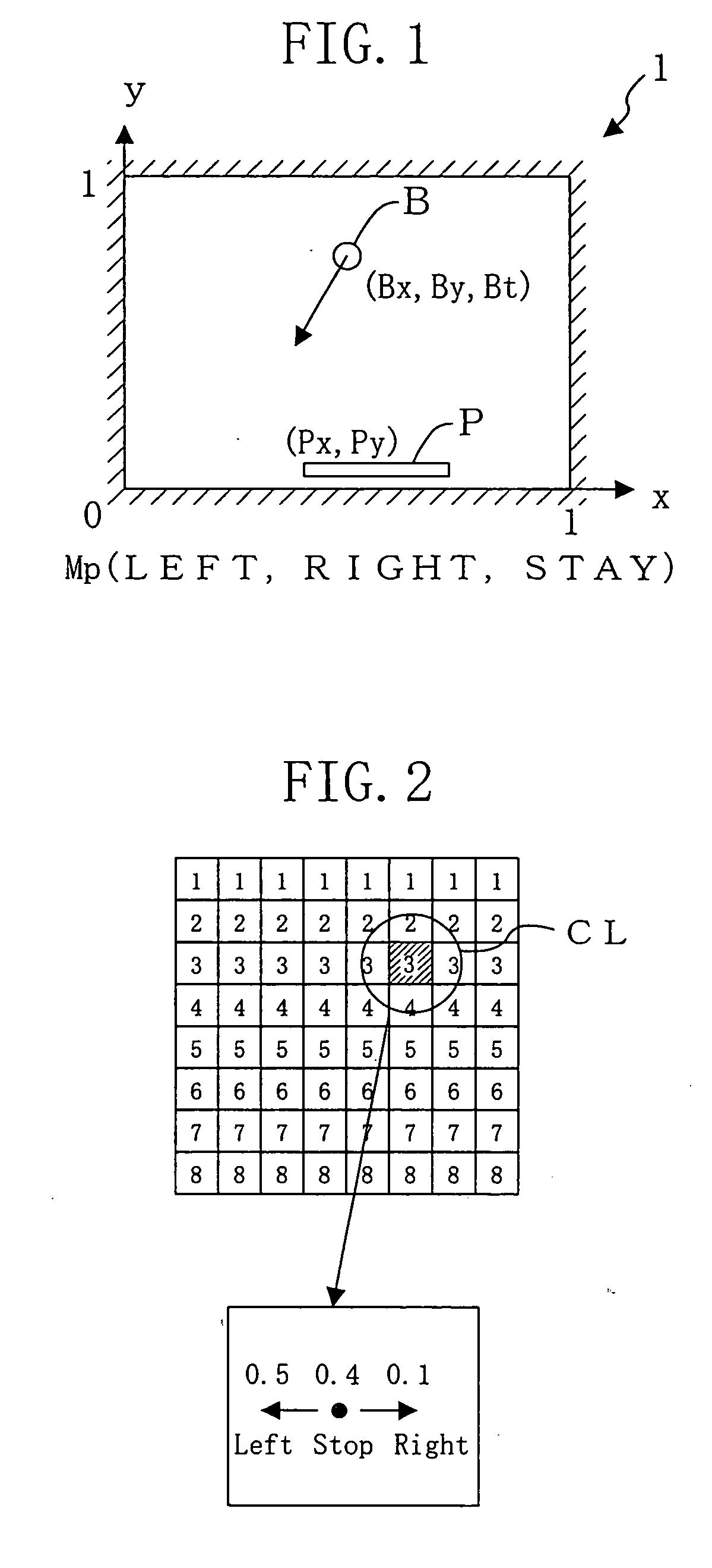
[0065] A state observation section 12 observes the state of the environment 11 and obtains state data indicating a current state. In this case, the state data is expressed as s(t). For the problem of FIG. 1, a state with respect to a ball B and a puddle P (Bx, By, Bt, Px) can be obtained as the state data s(t).
[0066] A environment prediction section 13 predicts a future state change with respect to the environment 11 based on the state data s(t) obtained by the state observation section 12. In this case, coordinates of the ball B (Bx, By)...
second embodiment
Modified Example of Second Embodiment
[0105] Moreover, in consideration of combinations with learning, a method in which a state at a time when a state value turns from an unlearned state to an already-learned state is determined as a target state can be used. Using this method, in a situation where learning has not proceeded so much, action determination can be performed based on a state value in the already-learned region while in an unlearned region, a future state in the already-learned region can be determined as a target state to perform action determination.
[0106] In the second embodiment, in the graph of FIG. 8, the timing when the state value starts decreasing is determined as a target state. However, to make it possible to determine a target state in this manner, state values have to be stored to reach a sufficient amount and this requires an enormous number of times of learning, depending on a problem.
[0107] In contrast, according to this modified example, a timing when ...
third embodiment
[0114] In the above-described embodiment, the respective functions of the prediction-based action determination sections 16 and 16A have been given beforehand. However, when it is difficult to give the action generation function beforehand, an action generation capability for making a state reach a target state has to be achieved. In this embodiment, the action generation capability is achieved by learning.
[0115]FIG. 9 is a diagram illustrating the internal configuration of a prediction-based action determination section 16A in the configuration of FIG. 6 according to this embodiment. In FIG. 9, the reference numeral 31 denotes a state-change-with-action detection section for receiving state data s(t) and detecting a state and an action in the previous step from a current state indicated by the state data s(t), the reference numeral 32 denotes a state-change-with-action storage section for storing, as a state change, the current state s(t) detected by the state-change-with-action d...
PUM
 Abstract
Description
Claims
Application Information