Steering column assembly

a technology for steering columns and assemblies, applied in steering controls, sliding contact bearings, vehicle mounted steering controls, etc., can solve problems such as hazards to drivers, and achieve the effects of less force, and reducing resistance to collaps

Inactive Publication Date: 2006-07-20
LUCAS AUTOMOTIVE GMBH
View PDF4 Cites 11 Cited by
  • Summary
  • Abstract
  • Description
  • Claims
  • Application Information

AI Technical Summary

Benefits of technology

[0007] As the loads on the steering column can be high in the event of a crash the clamp and the lever that allows it to be opened and closed must be quite robust and this often makes it a relatively large device. The location of the lever can in some cases present a hazard to the driver as it may be struck by the drivers legs causing possible injury. Providing an actuator and a switch removes the requirement for a lever and so reduces the level of risk to the driver. The designer has greater freedom over the location of the switch which can be moved to a more convenient position than a lever.
[0027] Upon detection of a collapse, the actuator control means may operate the actuator to rapidly release the clamp to an initial collapse position and subsequently to gradually unclamp the clamping mechanism over time providing a decreasing resistance to collapse. After a short period equal to the time for an airbag to inflate it may then hold the pin in a fixed position to maintain a constant force resisting collapse. After a further short period corresponding to the onset of deflation of the airbag the pin may be further released to reduce the force opposing collapse to an even lower level. The duration of each stage and the position of the clamp mechanism may be accurately controlled by the actuator control means.

Problems solved by technology

The location of the lever can in some cases present a hazard to the driver as it may be struck by the drivers legs causing possible injury.

Method used


Image

  • Steering column assembly
  • Steering column assembly
  • Steering column assembly

Examples


second embodiment

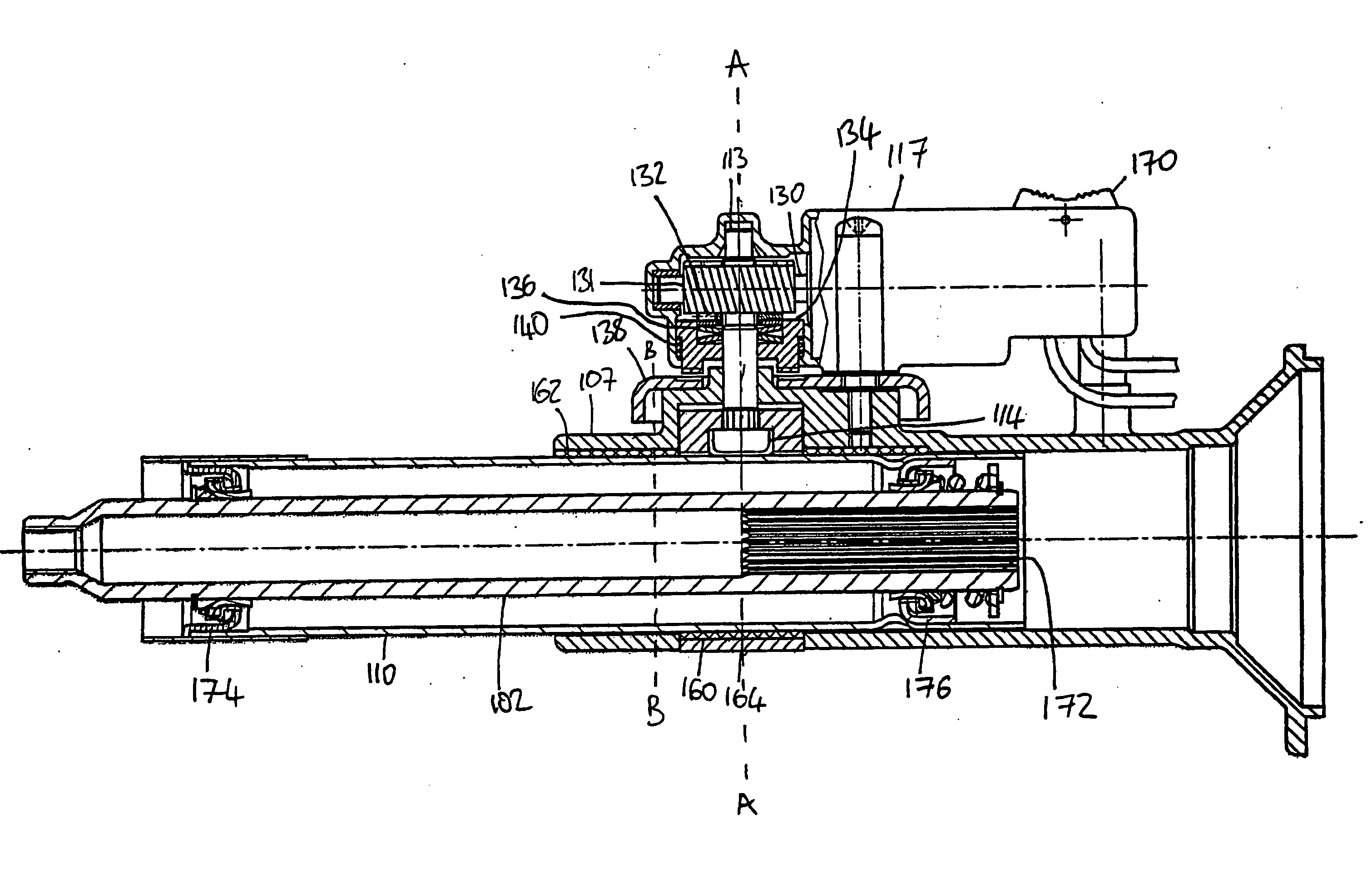
[0049] a steering assembly according to the present invention is shown in FIGS. 3 and 4 of the accompanying drawings. Similar features to those of the preceding embodiments have been given the same indicia incremented by 100.

first embodiment

[0050] The steering assembly of this embodiment is broadly similar to that of the preceding embodiment. In FIG. 4 of the accompanying drawings the lower shaft 101 has not been shown in order to show the splined reception 172 for the lower shaft 101 in the upper shaft 102. The figure also shows how the upper shroud 110 supports the upper shaft 102; upper 174 and lower 176 roller bearings support the upper shaft 102 towards the upper and lower ends of the upper shroud 110. A control switch 170 on motor 117 can also be seen. This instructs the motor to drive to unlock or lock the rake and reach adjustments at a driver's request. These features are equally applicable to the

[0051] The second embodiment differs in the mechanism by which the reach adjustment is locked. The method of locking the rake adjustment using a clamp block 134 onto a serrated mounting bracket 138 is the same as for the previous embodiment. The pin 113 lacks the toothed head 14 of that embodiment but instead has a re...


PUM


Abstract

A steering column assembly comprising a steering column shroud which supports a steering column shaft, the shroud being connected to the vehicle by a clamping mechanism which is operable between a locked position in which the shroud is clamped in position relative to a fixed portion of the vehicle chassis and an unlocked position in which the shroud is adjustable for reach and / or rake relative to the vehicle chassis. The clamping mechanism includes an actuator and a user operated switch that is connected to the actuator and which is operable to control the operation of the actuator to move the clamp between the locked and the unlocked position.

Description

CROSS-REFERENCE TO RELATED APPLICATIONS [0001] This application claims priority to application number PCT / IB2004 / 001263 filed Mar. 19, 2004, the disclosures of which are incorporated herein by reference in entirety, which claims priority to Great Britain Application No. 0307468.9 filed Apr. 1, 2003, the disclosures of which are incorporated herein by reference in entirety.BACKGROUND OF THE INVENTION [0002] This invention relates to improvements in steering column assemblies, especially but not exclusively to electric power assisted steering assemblies. [0003] It is known to provide a steering column assembly in which a steering wheel is connected to one or more road wheels through a collapsible or telescopic steering column shaft. The shaft is designed to collapse away from a driver of the vehicle if a load is applied to the steering wheel in the event of an accident. The shaft may comprise a single part shaft which has a weakened central section that will concertina under an axial ...

Claims


Application Information

Patent Timeline
Patent Type & Authority Applications(United States)
IPC IPC(8): B62D1/18B62D1/181B62D1/184
CPCB62D1/184F16C33/04F16C2326/24F16C27/02
Inventor CAMP, ECKART OP DEN
Owner LUCAS AUTOMOTIVE GMBH
Why Eureka
Try Eureka