Vibration device

a vibration device and rotary technology, applied in the direction of magnets, machine supports, magnets, etc., can solve the problems of rotary vibration devices, vibration force is in a radial direction relative to the axis of rotation of the motor, vibration amplitude cannot be modulated independently from vibration frequency, etc., to achieve the effect of increasing the resonance of the vibratory system

Active Publication Date: 2006-07-20
COACTIVE DRIVE CORP
View PDF48 Cites 23 Cited by
  • Summary
  • Abstract
  • Description
  • Claims
  • Application Information

AI Technical Summary

Benefits of technology

[0014] In another example the vibratory system further comprises a resonance circuit coupled to the driver circuit for increasing resonance of the vibratory system. In a further example the spring device is a nonlinear spring device. In this case the nonlinear spring device is desirably selected so that a resonant frequency of the vibratory system varies according to an amplitude of vibration.
[0015] In accordance with a further embodiment of the present invention, a method of controlling a vibration device is provided. Here, the vibration device may include a coil for generating an electromagnetic field and affixed to a body, a moveable mass of magnetic m...

Problems solved by technology

A disadvantage of such vibrating devices is that the frequency of vibration is coupled to the vibration amplitude; thus, the vibration amplitude cannot be modulated independe...

Method used


Image

  • Vibration device
  • Vibration device
  • Vibration device

Examples


Embodiment Construction

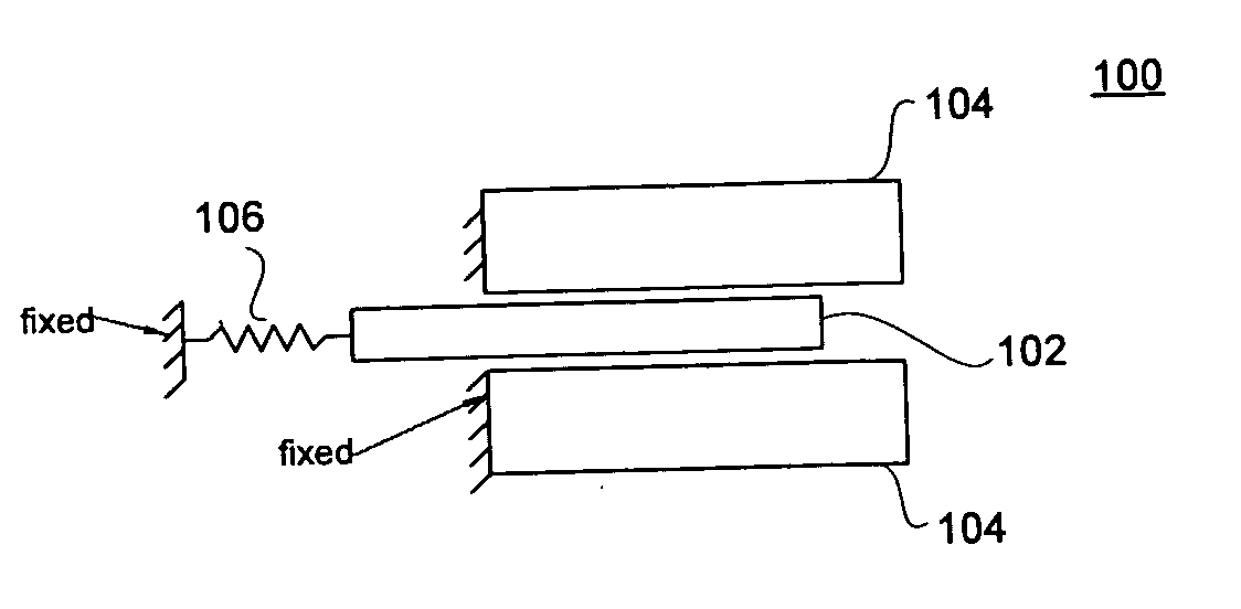
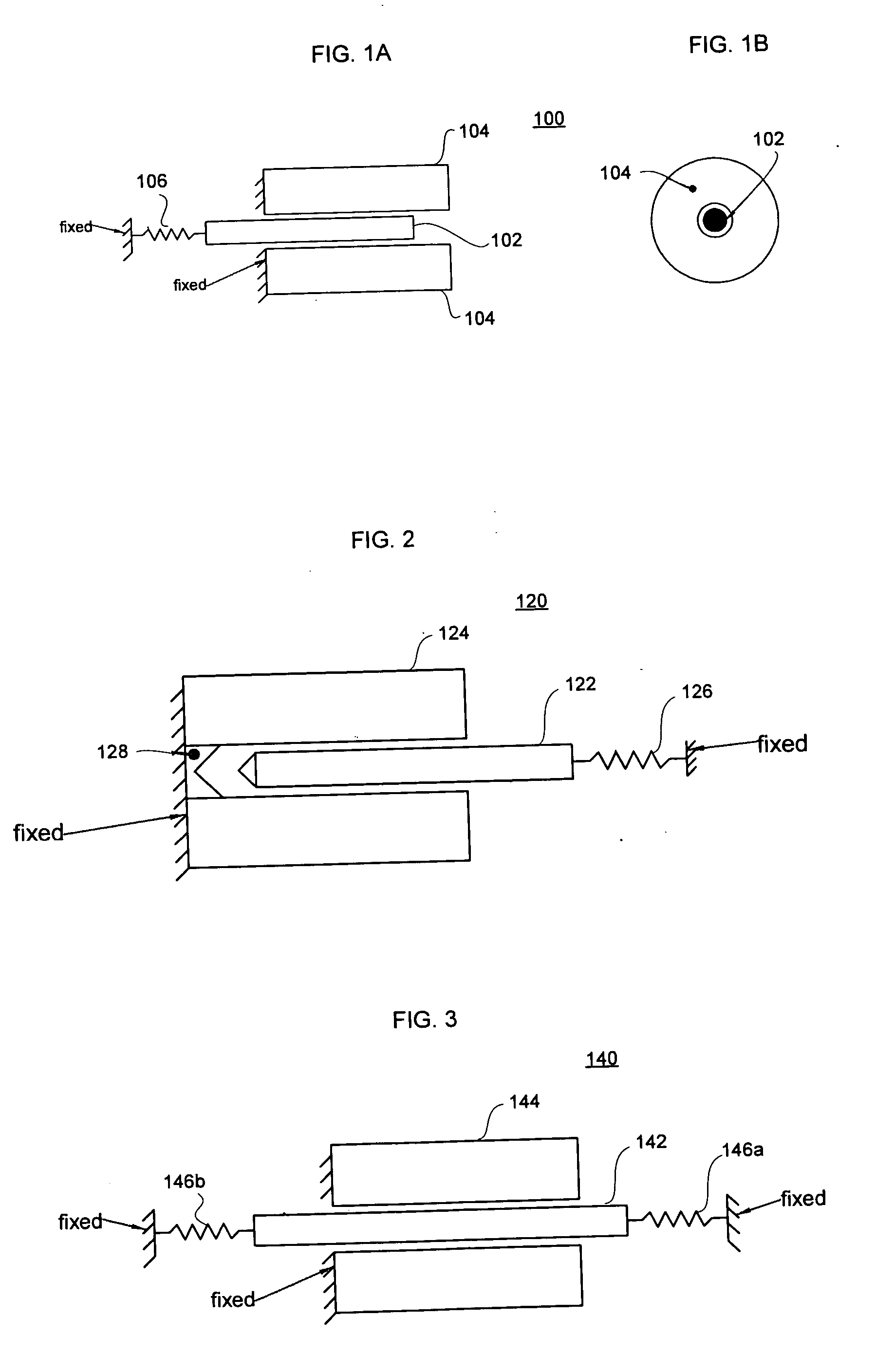
[0031] An embodiment of the invention is show in FIGS. 1A-B. As seen in the side view of FIG. 1A, vibration device 100 includes a moveable mass such as plunger 102 surrounded by a coil 104. Preferably, the plunger 102 is substantially or completely encircled by the coil 104. The plunger 102 is attached at one end to a spring device 106, and the spring device 106 is fixed relative to a body (not shown) onto which a vibration force is being applied. The coil 104 is also fixed relative to the body onto which a vibration force is being applied.

[0032] The coil 104 and plunger 102 typically have a round cross section, as seen in FIG. 1B. The coil 104 is an electromagnetic coil and can generate an electromagnetic field when current runs through it. The plunger 102 can be made of ferromagnetic material, permanent magnet material, a combination of permanent magnetic and ferromagnetic materials, and / or materials capable of responding to exert a force in response to exposure of the material t...


PUM


Abstract

The present invention pertains to vibration devices that do not require a rotating mass. In accordance with aspects of the invention, a coil causes a plunger to move linearly. A spring device is coupled to one end of the plunger. Activation of the coil causes the plunger to move in a first direction relative to a body and coil deactivation enables the spring device to move the plunger in an opposite direction relative to the body. Activating the coil at a predetermined frequency causes vibration of the plunger. Vibratory forces are transferred via the spring device and coil onto the body at predetermined locations. Opposing spring devices may be affixed to either end of the plunger. Spring devices may be linear or non-linear. Such spring devices may be used in conjunction with magnetic spring devices. A controller and a driver circuit may be used to control system operation.

Description

CROSS REFERENCE TO RELATED APPLICATIONS [0001] This application claims the benefit of the filing date of U.S. Provisional Patent Application No. 60 / 641,317 filed Jan. 4, 2005 and entitled “VIBRATION DEVICE,” the entire disclosure of which is hereby expressly incorporated by reference herein.BACKGROUND OF THE INVENTION [0002] The present invention relates generally to vibration devices and more particularly to non-rotary vibration devices. [0003] Vibration devices are used to provide tactile feel in devices such as pagers and telephones. Vibration devices can also be used to provide tactile feedback for computer interfaces and game controllers. Vibration devices can also be used to transfer energy and for vibratory feeders. [0004] Some existing vibration devices are rotary actuators with an eccentric mass. In these devices, the vibration force is proportional to the velocity squared of the rotating mass. A disadvantage of such vibrating devices is that the frequency of vibration is c...

Claims


Application Information

Patent Timeline
IPC IPC(8): F16M13/00
CPCH01F7/1615H02K33/02
Inventor DELSON, NATHAN
Owner COACTIVE DRIVE CORP
Why Eureka
Try Eureka