Apparatus for removing noise of video signal

a video signal and apparatus technology, applied in the field of apparatus for removing video signal noise, can solve the problems of insufficient removal of video signal noise, inability to provide correct processing, and major factors of image quality degradation, so as to achieve effective estimation of noise level and remove video signal noise

Inactive Publication Date: 2006-07-20
LG ELECTRONICS INC
View PDF5 Cites 39 Cited by
  • Summary
  • Abstract
  • Description
  • Claims
  • Application Information

AI Technical Summary

Benefits of technology

[0016] An object of the present invention is to provide an apparatus for removing a noise of a video signal, by which a noise level can be effectively estimated to enhance an image quality of the video signal.
[0017] Another object of the present invention is to provide an apparatus for removing a noise of a video signal, by which the noise can be removed in a manner of effectively estimating a noise level though motion adaptive filtering.
[0018] Another object of the present invention is to provide an apparatus for removing a noise of a video signal, by which blurring is prevented in the process of removing the noises.

Problems solved by technology

Generally, there always exist various noises such as a thermal noise of a camera, a noise in a transmission process and the like in a TV video signal.
And, theses noises are the major factors of image quality degradation.
In doing so, if a level of a noise appended to a video is unknown, the processing cannot provide a correct result.
On the other hand, if a weak noise removal processing is carried out on a video having a big noise, it is unable to sufficiently remove the noise appended to the video.
However, by theses methods, a fine component of a video is blurred.

Method used


Image

  • Apparatus for removing noise of video signal
  • Apparatus for removing noise of video signal
  • Apparatus for removing noise of video signal

Examples


first embodiment

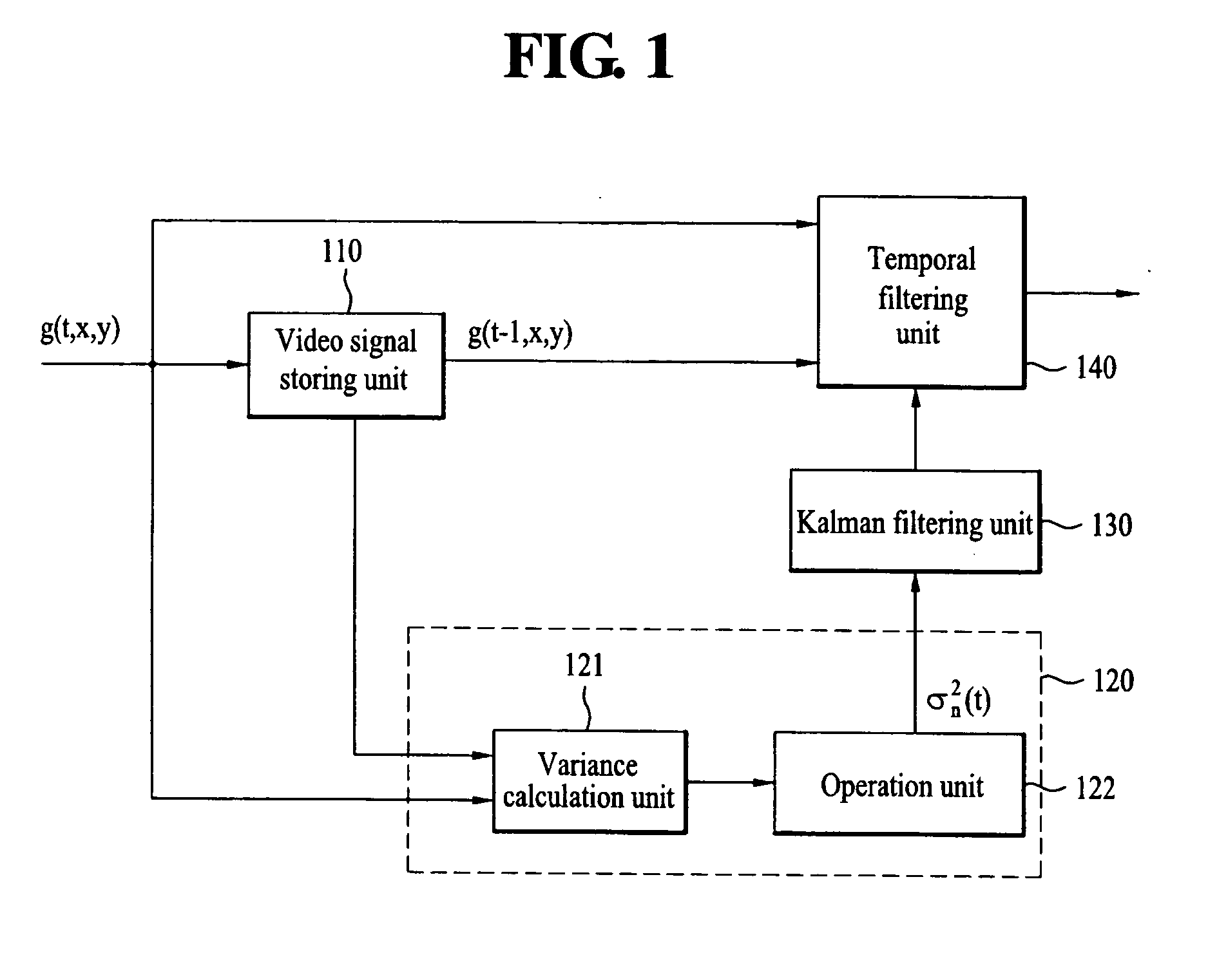
[0042]FIG. 1 is a block diagram of an apparatus for removing a noise of a video signal according to a first embodiment of the present invention.

[0043] Referring to FIG. 1, an apparatus for removing a noise of a video signal according to a first embodiment of the present invention includes a video signal delay unit 110, a temporal noise level estimation unit 120, a Kalman filtering unit 130 and a temporal filtering unit 140.

[0044] In the above-configured apparatus, a current input video is provided to the video signal storing unit 110, the temporal noise level estimation unit 120 and the temporal filtering unit 140.

[0045] The video signal storing unit 110 delays the input video by a frame unit and then outputs the delayed signal to the temporal noise level estimation unit 120 and the temporal filtering unit 140.

[0046] The temporal noise level estimation unit 120 includes an operation unit 121 finding an absolute value of a frame difference between brightness values of two tempora...

second embodiment

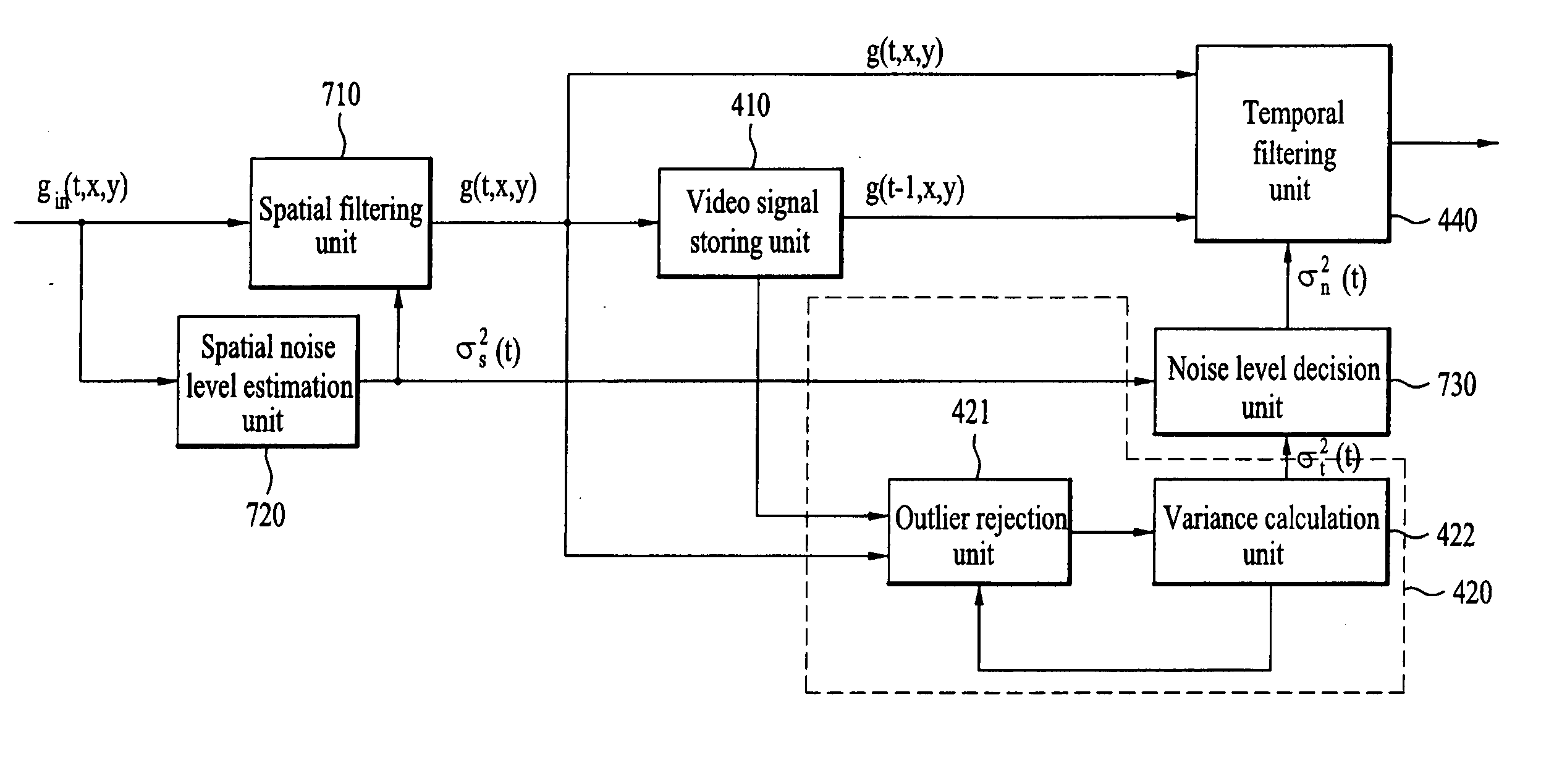
[0078]FIG. 4 is a block diagram of an apparatus for removing a noise of a video signal according to a second embodiment of the present invention.

[0079] Referring to FIG. 4, an apparatus for removing a noise of a video signal according to a second embodiment of the present invention includes a video signal storing unit 410, a temporal noise level estimation unit 420, a Kalman filtering unit 430 and a temporal filtering unit 440.

[0080] The second embodiment of the present invention differs from the first embodiment of the present invention in an estimation process of the temporal noise level estimation unit 420.

[0081] The temporal noise level estimation unit 420 receives a difference between two temporally consecutive video signals, calculates a variance of a noise, from which a noise component exceeding a specific level is removed, among noises generated from a video motion between two timing points, and then outputs the calculated variance.

[0082] Namely, a video signal, i.e., a ...

third embodiment

[0100]FIG. 5 is a block diagram of an apparatus for removing a noise of a video signal according to a third embodiment of the present invention.

[0101] Referring to FIG. 5, an apparatus for removing a noise of a video signal according to a third embodiment of the present invention includes a video signal storing unit 510, a spatial noise level estimation unit 520, a temporal noise level estimation unit 530, a global motion detection unit 540, a Kalman filtering unit 550 and a temporal filtering unit 560.

[0102] A current input video is provided to the video signal storing unit 510, the spatial noise level estimation unit 520, the temporal noise level estimation unit 530 and the temporal filtering unit 560.

[0103] The video signal storing unit 510 delays an input video by a frame unit and them outputs the delayed signal to the spatial noise level estimation unit 520, the temporal noise level estimation unit 530 and the temporal filtering unit 560.

[0104] The temporal noise level esti...


PUM


Abstract

An apparatus for removing a noise of a video signal is disclosed, by which a noise level can be effectively estimated to enhance an image quality of the video signal, by which the noise can be removed in a manner of effectively estimating a noise level though motion adaptive filtering, and by which blurring is prevented in the process of removing the noises. The present invention includes a temporal noise level estimation unit estimating a level of a temporal noise included in the video signal using a difference between two temporally consecutive videos, a noise correction unit correcting a noise estimated by the temporal noise level estimation unit, and a noise removal unit removing the noise included in the video signal using a level of the corrected noise.

Description

[0001] This application claims the benefit of the Korean Patent Application No. 10-2005-0004498, filed on Jan. 18, 2005 and the Korean Patent Application No. 10-2005-0091446, filed on Sep. 29, 2005, which are hereby incorporated by reference as if fully set forth herein. BACKGROUND OF THE INVENTION [0002] 1. Field of the Invention [0003] The present invention relates to a broadcast receiver, and more particularly, to an apparatus for removing a noise of a video signal. Although the present invention is suitable for a wide scope of applications, it is particularly suitable for noise reduction of the video signal. [0004] 2. Discussion of the Related Art [0005] Generally, there always exist various noises such as a thermal noise of a camera, a noise in a transmission process and the like in a TV video signal. And, theses noises are the major factors of image quality degradation. [0006] Hence, a TV receiving unit or the like carries out such a processing as a noise removal and the like....

Claims


Application Information

Patent Timeline
Patent Type & Authority Applications(United States)
IPC IPC(8): H04N5/21
CPCH04N5/21
Inventor RHEE, KWANG YEON
Owner LG ELECTRONICS INC
Why Eureka
Try Eureka