Light zoom source using light emitting diodes and an improved method of collecting the energy radiating from them

a technology of light-emitting diodes and zoom-emitting sources, which is applied in the field of apparatus and a method of collecting the energy radiating from them, can solve the problems of bulk and form losses, energy loss or not being collected into a useful beam, and the proportion of the energy radiated from the led junction is leaked through the walls of the package,

Active Publication Date: 2006-07-20
SIGNIFY HLDG BV
View PDF3 Cites 61 Cited by
  • Summary
  • Abstract
  • Description
  • Claims
  • Application Information

AI Technical Summary

Benefits of technology

[0030] Additionally, as used herein, the term “light source” should be understood to include all illumination sources, including, but not limited to, LED-based sources as defined above, incandescent sources (e.g., filament lamps, halogen lamps), pyro-luminescent sources (e.g., flames), candle-luminescent sources (e.g., gas mantles), carbon arc radiation sources, photo-luminescent sources (e.g., gaseous discharge sources), fluorescent sources, phosphorescent sources, high-intensity discharge sources (e.g., sodium vapor, mercury vapor, and metal halide lamps), lasers, electro-luminescent sources, cathode luminescent sources using electronic satiation, galvano-luminescent sources, crystallo-luminescent sources, kine-luminescent sources, thermo-luminescent sources, triboluminescent sources, sonoluminescent sources, radioluminescent sources, and luminescent polymers capable of producing primary colors.
[0031] For purposes of the present disclosure, the term “light” sh

Problems solved by technology

In TIR systems, some portion of the energy radiated from the LED junction is leaked through the walls of the package and remains uncontrolled.
Additionally, there are bulk and form losses as well.
In system

Method used


Image

  • Light zoom source using light emitting diodes and an improved method of collecting the energy radiating from them
  • Light zoom source using light emitting diodes and an improved method of collecting the energy radiating from them
  • Light zoom source using light emitting diodes and an improved method of collecting the energy radiating from them

Examples


Embodiment Construction

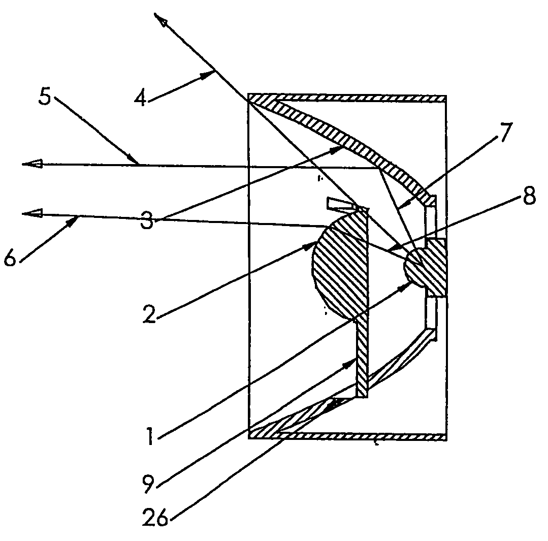
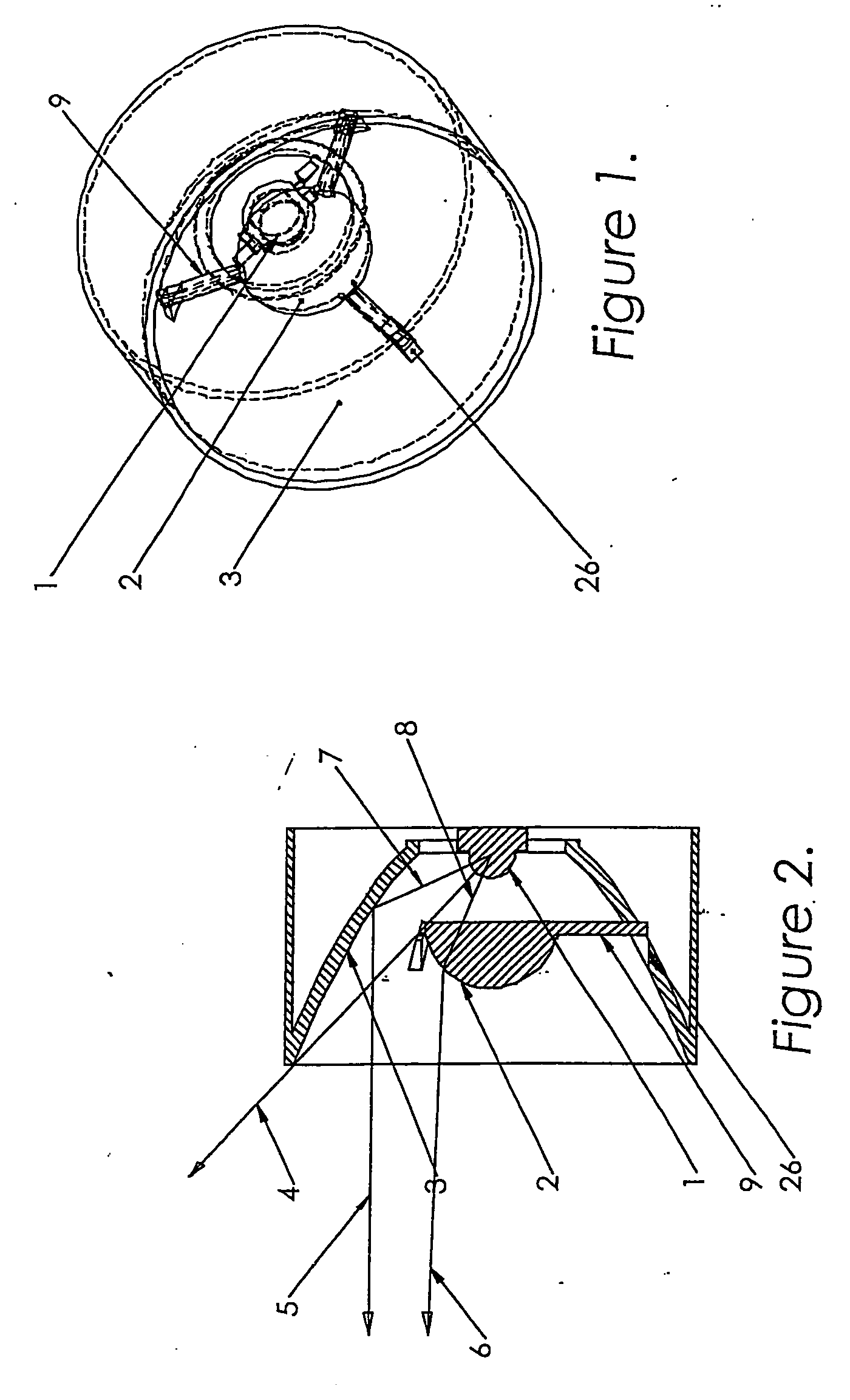
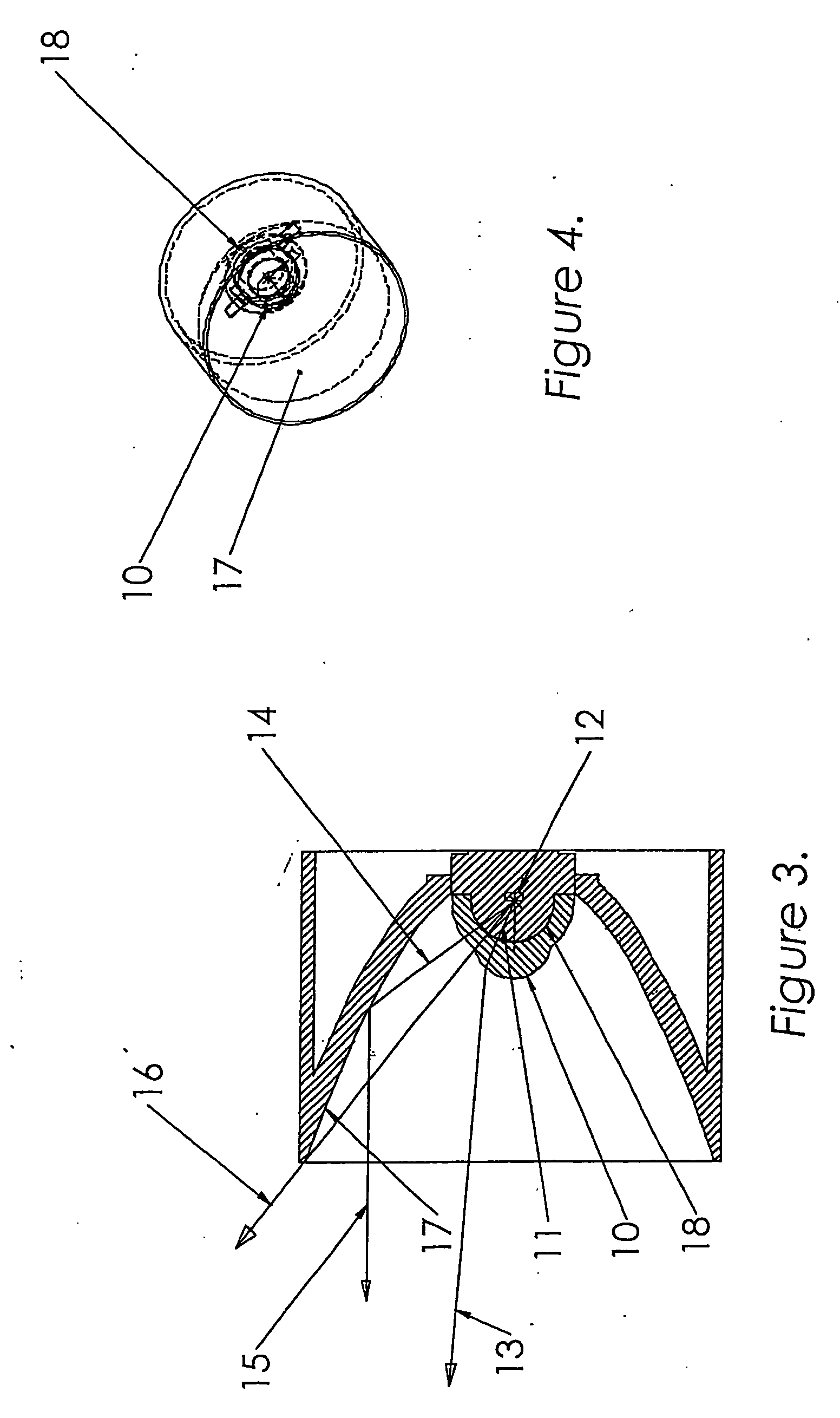
[0042] In FIGS. 1-4 a device incorporating the invention is generally denoted by reference numeral 24. LED source 1 is shown as packaged in a conventional package, which is comprised of a substrate in which the light emitting junction is defined encapsulated in a transparent epoxy or plastic housing formed to provide a front hemispherical front dome or lens(es) over the light emitting junction or chip. Many different types and shapes of packages could be employed by an LED manufacturer and all types and shapes are included within the scope of the invention. Hereinafter in the specification the term, “LED source 1 ” and in another embodiment as “LED source 18”, shall be understood to include the passivating package in which the light emitting junction or chip is housed. Various means for thermal management of source 1 may also be included, which is shown as a thermally conductive connector base 17 in FIGS. 5b and 5c, which is thermally coupled to other heat sinks or finned bodies as ...


PUM


Abstract

An apparatus is comprised of a light source radiating into a peripheral forward solid angle and a center forward solid angle. A reflector is positioned to reflect light from the light source from the peripheral forward solid angle into a longitudinal beam about an optical axis of the reflector. A lens is disposed longitudinally forward of the light source for focusing light into a predetermined beam pattern from the center forward solid angle into a skewed beam in a skewed direction with respect to the optical axis of the reflector to project a composite beam of light comprised of the light radiated in the skewed beam and the longitudinal beam.

Description

RELATED APPLICATIONS [0001] The present application is related to U.S. Provisional Patent Application, Ser. No. 60 / 638,956, filed on Dec. 23, 2004, which is incorporated herein by reference and to which priority is claimed pursuant to 35 USC 119.BACKGROUND OF THE INVENTION [0002] 1. Field of the Invention [0003] The invention relates the field of light sources using light emitting diodes (LEDs) and in particular to an apparatus and a method of collecting the energy radiating from them. The device could be used in general lighting, decorative and architectural lighting, portable and nonportable lighting, emergency lighting, fiber optic illumination and many other applications. [0004] 2. Description of the Prior Art [0005] Typically in the prior art LED light source either a lens or a reflector is used to collect most of the 2π steradians front solid angle or forward hemispherical wavefront of light radiating from an LED. Recall that the solid angle Ω subtended by a surface S is defin...

Claims


Application Information

Patent Timeline
IPC IPC(8): F21V7/00
CPCF21S2/00F21V5/04F21V14/02F21V14/04F21V14/06F21V17/02F21Y2115/10
Inventor HOLDER, RONALDRHOADS, GREG
Owner SIGNIFY HLDG BV
Why Eureka
Try Eureka