Drive control system for automotive vehicle

a technology for controlling system and vehicle, applied in anti-collision system, non-deflectable wheel steering, underwater vessels, etc., to achieve the effect of improving security

Inactive Publication Date: 2006-07-20
DENSO CORP
View PDF7 Cites 18 Cited by
  • Summary
  • Abstract
  • Description
  • Claims
  • Application Information

AI Technical Summary

Benefits of technology

[0007] The present invention has been made in view of the above-mentioned problem, and an object of the present invention is to provide an improved drive control system for an a

Problems solved by technology

For example, a wall along a curved road that makes a blind

Method used


Image

  • Drive control system for automotive vehicle
  • Drive control system for automotive vehicle
  • Drive control system for automotive vehicle

Examples


first embodiment

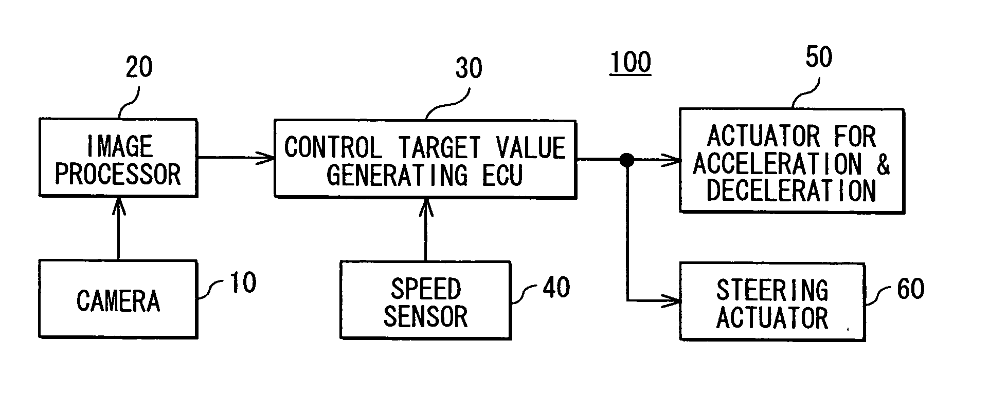
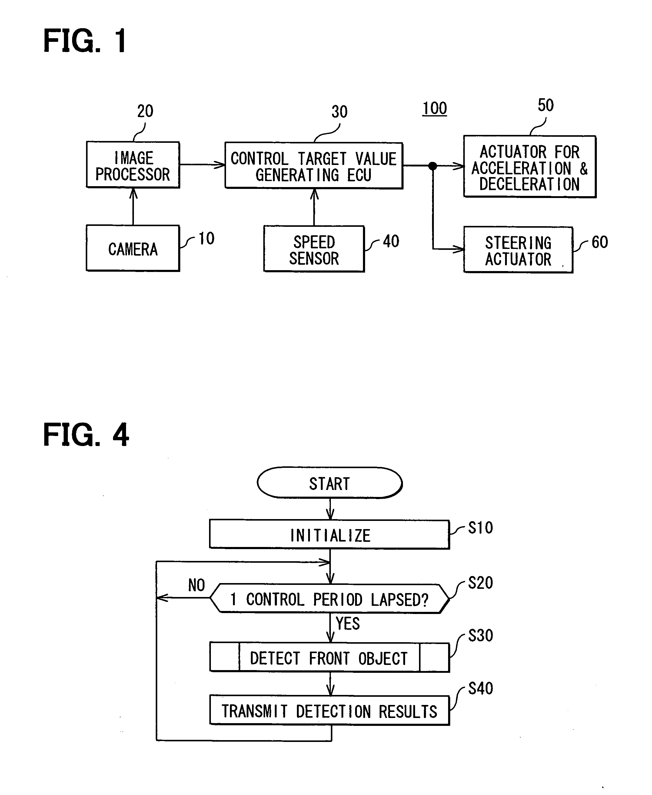
[0029] the present invention will be described with reference to accompanying drawings. As shown in FIG. 1, a drive control system 100 is composed of an on-board camera 10, an image processor 20, an electronic control unit (ECU) 30 for generating target control values, a speed sensor 40 for detecting a driving speed of an own vehicle, an actuator 50 for controlling acceleration or deceleration, and a steering actuator 60.

[0030] The camera 10 is mounted on a front portion of a vehicle for taking images in front of the vehicle. The image processor 20 processes the images taken by the camera 10 to formulate information regarding front objects and own vehicle in a driving lane. The information is fed to the ECU 30 for generating the target control values. The ECU 30 is composed of a microcomputer that generates target control values to be fed the actuators 50, 60. That is, the ECU 30 sets a target driving time up to a preceding vehicle Tt (Tt=Dbet / Vown, where Dbet is a distance between ...

second embodiment

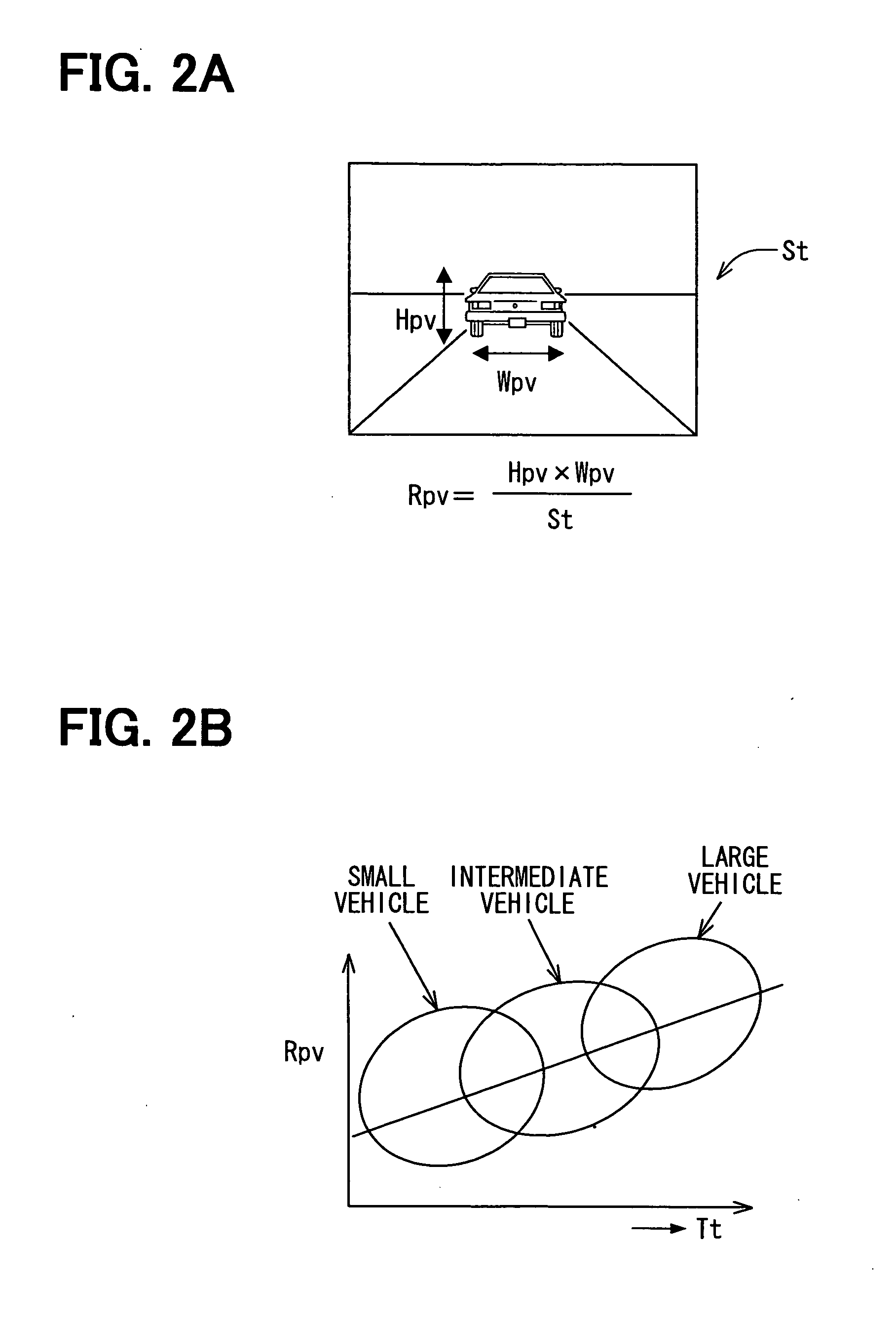
[0054] The vehicle control system 100 as the present invention controls the driving speed and the lateral position in the driving lane based on the back side area of a preceding vehicle. Since the vision field of a driver is more hindered as the size of the preceding vehicle is larger, the driving speed and the lateral position are controlled according to the back side area Sb of the preceding vehicle. A proper vision field of a driver is secured, and accordingly the driver feels safely in driving.


PUM


Abstract

In a drive control system, a front image taken by a camera is processed by an image processor, and an electronic control unit generates control target values according to outputs from the image processor. Actuators control a driving speed and/or a lateral position of an own vehicle in a driving lane, based on the control target values. Front obstacles, such as a preceding vehicle, a blind curve and an uphill road, are included in a front image, and a ratio of the front obstacle occupying a front vision field is calculated. The vehicle is controlled based on information including various obstacles located in front of the vehicle to thereby give an improved security to a driver.

Description

CROSS-REFERENCE TO RELATED APPLICATION [0001] This application is based upon and claims benefit of priority of Japanese Patent Application No. 2005-8172 filed on Jan. 14, 2005, the content of which is incorporated herein by reference. BACKGROUND OF THE INVENTION [0002] 1. Field of the Invention [0003] The present invention relates to a system for controlling drive of an automotive vehicle. [0004] 2. Description of Related Art [0005] An automatic drive control system, which sets a distance between an own vehicle and a preceding vehicle to a longer distance when the preceding vehicle is a large vehicle, is proposed by JP-A-2-40798. This system includes two sonar detectors, i.e., one sonar detector that transmits ultrasonic waves toward a preceding vehicle with an upward angle and the other sonar detector that transmits ultrasonic waves in a horizontal direction. Distances to the preceding vehicle from an own vehicle detected by two sonar detectors are compared, and it is determined th...

Claims


Application Information

Patent Timeline
IPC IPC(8): B62D6/00B60R1/00B60R21/00B60W10/00B60W10/04B60W10/06B60W10/18B60W10/184B60W10/20B60W30/00B60W30/16B62D101/00B62D137/00
CPCB62D15/026B62D15/0265G08G1/16G08G1/167G08G1/166
Inventor KUMON, HIROAKITAMATSU, YUKIMASAOGAWA, TAKASHI
Owner DENSO CORP
Why Eureka
Try Eureka