
Data reader and methods for imaging targets subject to specular reflection

a data reader and target technology, applied in the field of imaging targets subject to specular reflection, can solve problems such as ineffective detection, and achieve the effects of minimizing minimizing or eliminating specular reflection (over-saturated regions of sensor arrays), and reducing or eliminating specular reflection

Active Publication Date: 2006-07-27
DATALOGIC SCANNING
View PDF30 Cites 172 Cited by
  • Summary
  • Abstract
  • Description
  • Claims
  • Application Information

AI Technical Summary

Problems solved by technology

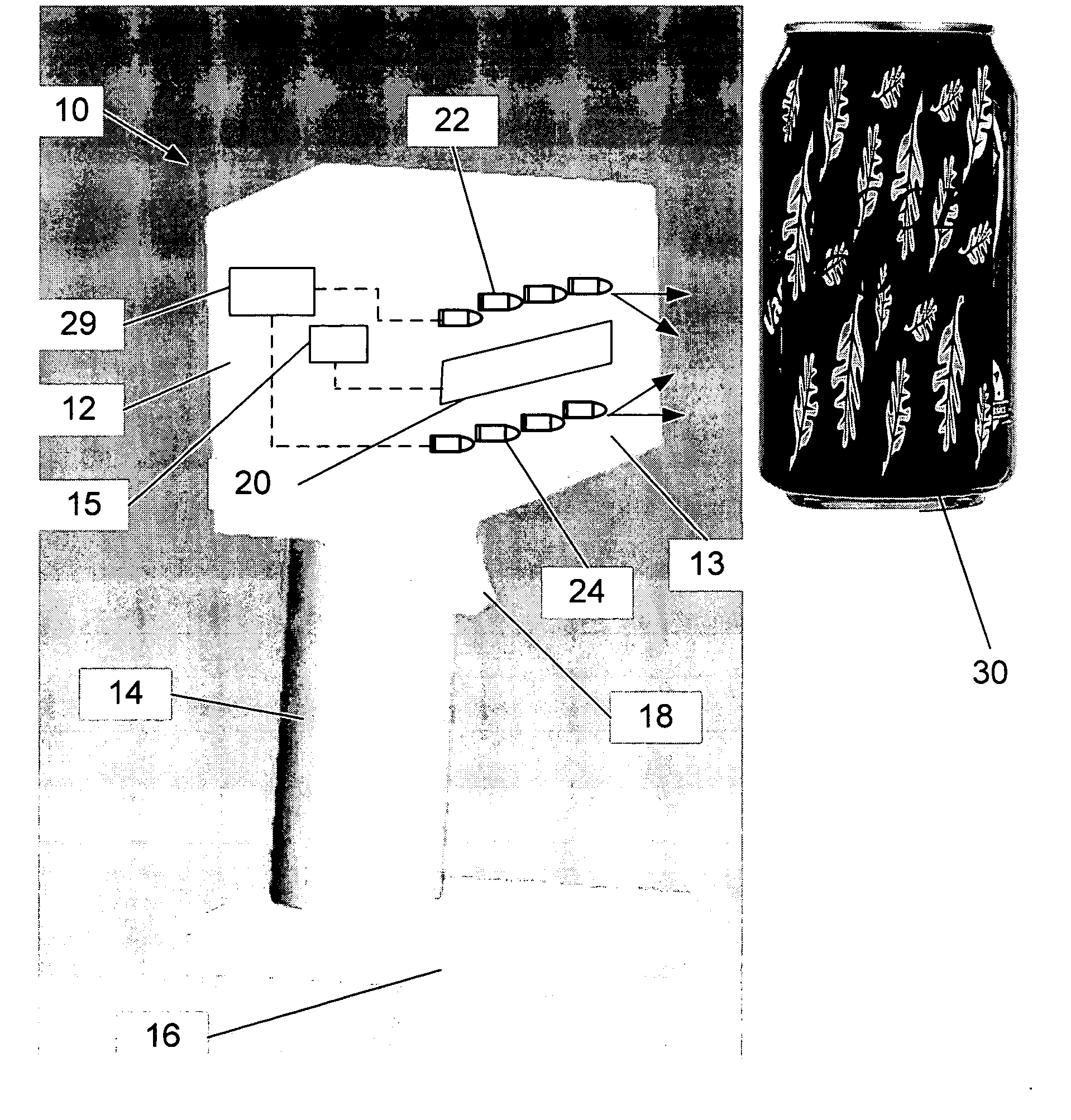
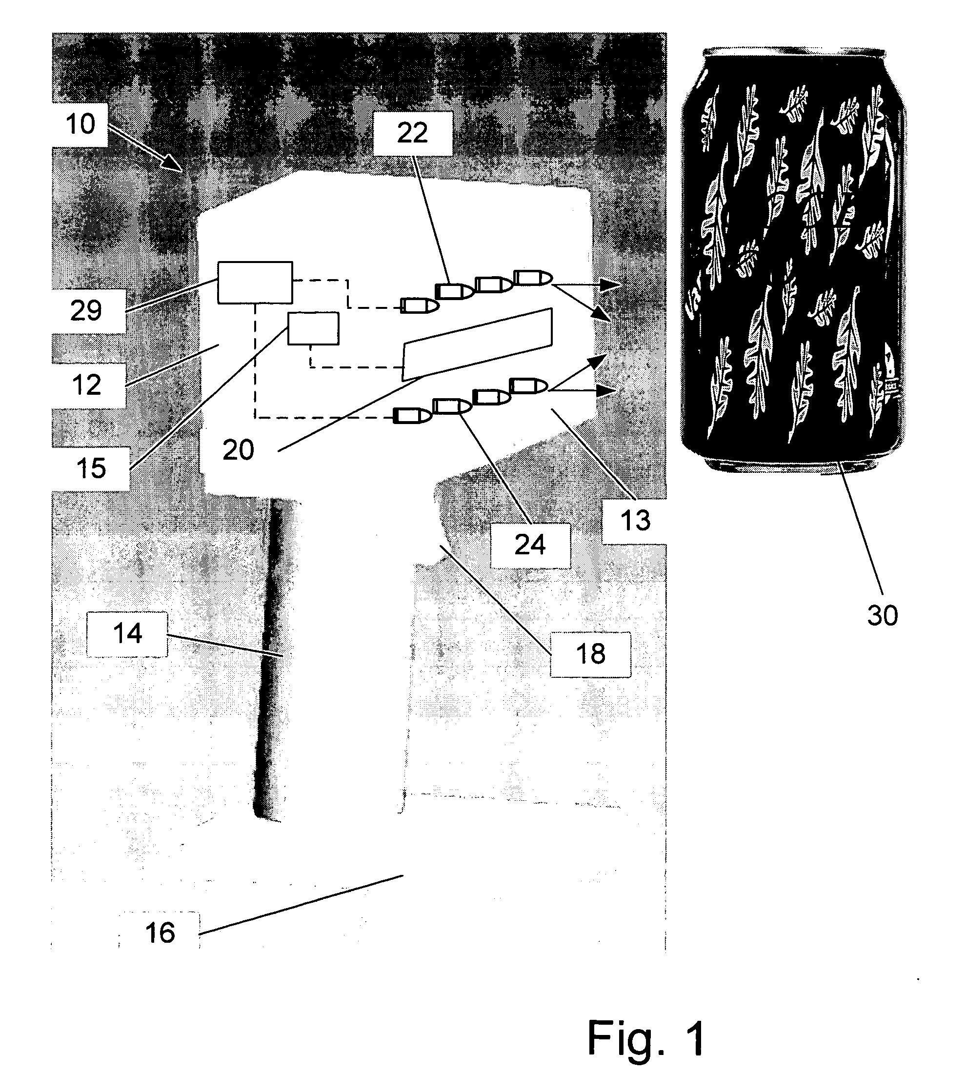
The present inventors have recognized that light from high-intensity illumination can reflect off certain surfaces such as metal cans creating a specular reflection of too high an intensity thereby oversaturating the sensor array resulting in ineffective detection.

Method used


Image

  • Data reader and methods for imaging targets subject to specular reflection
  • Data reader and methods for imaging targets subject to specular reflection
  • Data reader and methods for imaging targets subject to specular reflection

Examples


Embodiment Construction

[0019] Throughout the specification, reference to “one embodiment,” or “an embodiment,” or “some embodiments” means that a particular described feature, structure, or characteristic is included in at least one embodiment. Thus appearances of the phrases “in one embodiment,”“in an embodiment,” or “in some embodiments” in various places throughout this specification are not necessarily all referring to the same embodiment. Furthermore, the described features, structures, characteristics, and methods may be combined in any suitable manner in one or more embodiments. In view of the disclosure herein, those skilled in the art will recognize that the various embodiments can be practiced without one or more of the specific details or with other methods, components, materials, or the like. In other instances, well-known structures, materials, or operations are not shown or not described in detail to avoid obscuring aspects of the embodiments.

[0020] Preferred embodiments will now be describ...


PUM


Abstract

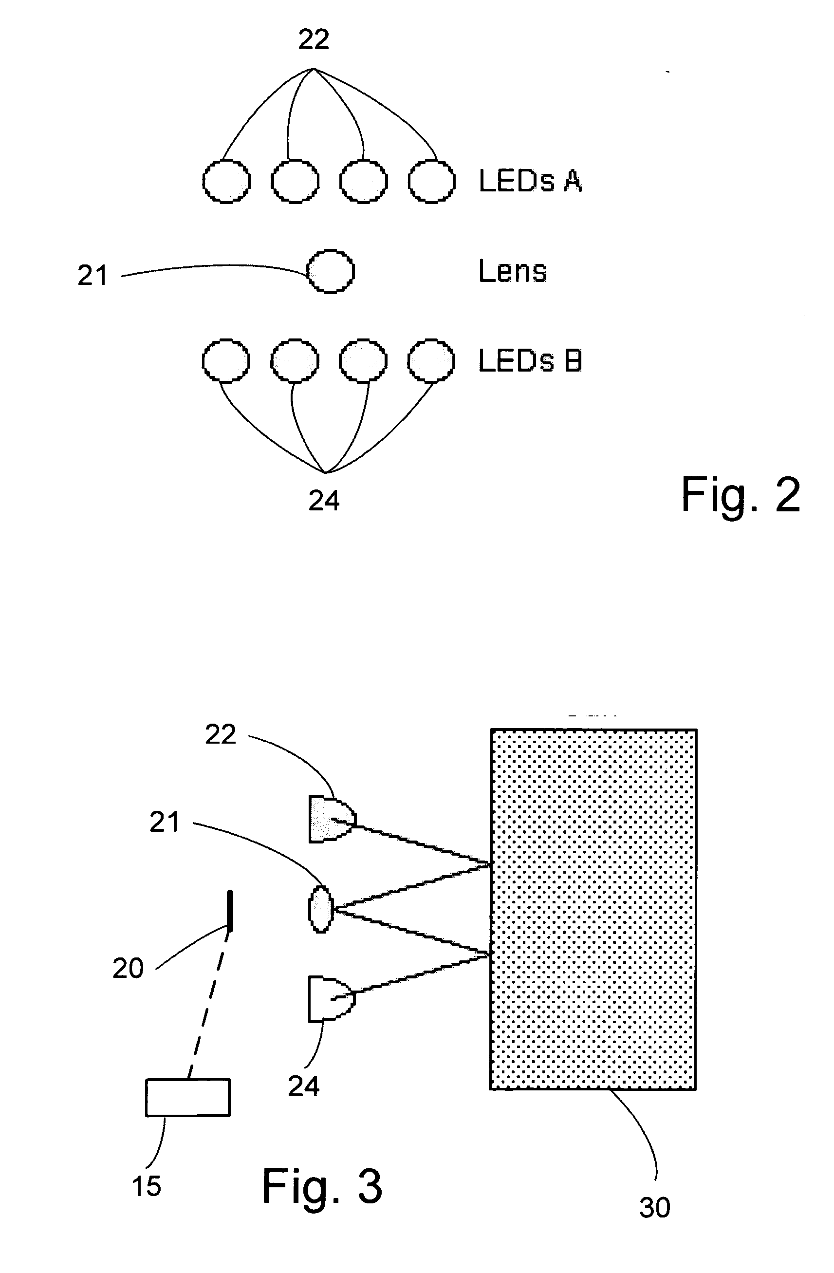
A data reader such as for example an imaging reader with a CCD or CMOS imager or the like, having multiple images of a target item illuminated or acquired from different directions in which the image signals are combined into a complete image of the item or selected portions of the item being read such that specular reflection (over-saturated regions of the sensor array) are minimized or eliminated. In one example data reader configuration, multiple illumination sources such as first and second rows of light emitting diodes (LED's) are aimed at the item being scanned from different directions. The illumination sources are alternately pulsed and return signals are collected at one or more sensor arrays. A selected non-saturated return signal from one of the illumination sources, or selected non-saturated portions of return signal from both of the illumination sources are processed to generate a complete non-saturated image of the target. In one preferred processing scheme, assuming that each of the LED's is capable of illuminating the entire target (e.g. a barcode), a pixel-by-pixel minimum is taken of the two images thereby producing an image with specular reflection minimized or nearly eliminated.

Description

BACKGROUND [0001] The field of this disclosure relates to imaging and collection devices and in particular to methods and devices for illumination, collection and imaging for optical code reading and other data and image capture devices. [0002] Image capture and other data reading devices are used to read optical codes, acquire data, and capture a variety of images. One common data acquisition device is an optical code reader. Optical codes typically comprise a pattern of dark elements and light spaces. There are various types of optical codes, including 1-D codes (such as UPC and EAN / JAN barcodes) and 2-D codes (such as PDF-417 and Maxicode). For convenience, some embodiments are described herein with reference to capture of 1-D barcodes. However, the embodiments may also be useful for other optical codes and symbols as well as other images such as fingerprint capture, and nothing herein should be construed as limiting this disclosure to optical codes or particular types of codes. ...

Claims


Application Information

Patent Timeline
Patent Type & Authority Applications(United States)
IPC IPC(8): G06K7/10
CPCG06K7/10752G06K7/14G06K7/1465H04N1/02865H04N1/40056
Inventor OLMSTEAD, BRYAN L.SMITH, LARRY JAMES
Owner DATALOGIC SCANNING
Learn More