Atomizer cooling by liquid circulation through atomizer tip holder

a technology of liquid circulation and atomizer, which is applied in the field of atomizers, can solve the problems of difficult routing of cooling water to the atomizer, high cost, and inability to meet the needs of atomization,

Active Publication Date: 2006-07-27
SOUTHWEST RES INST
View PDF25 Cites 4 Cited by
  • Summary
  • Abstract
  • Description
  • Claims
  • Application Information

AI Technical Summary

Problems solved by technology

However, in some applications, such as fuel injection atomizers, the atomization is intermittent.
Overheating of the liquid in the atomizer under...

Method used


Image

  • Atomizer cooling by liquid circulation through atomizer tip holder
  • Atomizer cooling by liquid circulation through atomizer tip holder
  • Atomizer cooling by liquid circulation through atomizer tip holder

Examples


Embodiment Construction

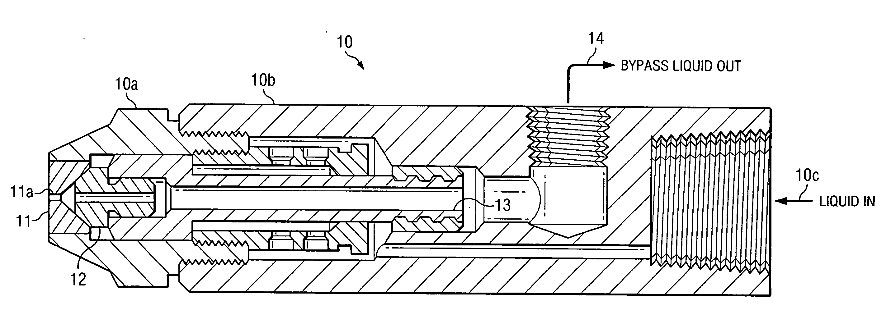
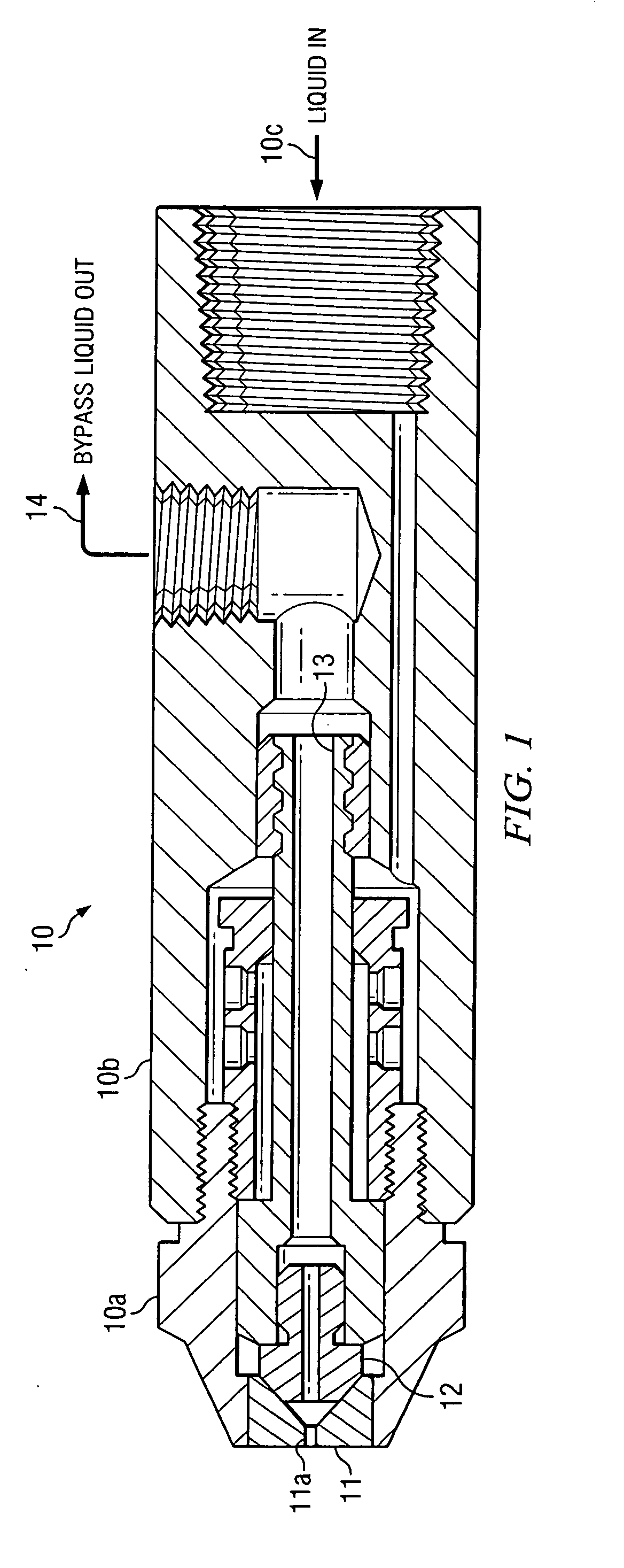
[0012] The concept discussed herein is directed to an atomizer design that reduces the chance of atomizer plugging, whether the liquid being sprayed is fuel, urea-water mixtures, or some other liquid or liquid mixture that is subject to thermal degradation. This concept may be implemented as an improvement to an existing, commercially available atomizer. The concept reduces or eliminates the probability of thermal degradation of the liquid being sprayed, while extending the flow range of the atomizer.

[0013]FIG. 1 illustrates an example of the type of atomizer with which the invention may be used. This atomizer 10 is the commercially available pressure-atomized Variflo™ bypass nozzle, available from Delavan Spray Technologies. Atomizer 10 comprises a nozzle 10a screwed into an adapter 10b. In accordance with the bypass design of atomizer 10, with constant supply pressure at inlet 10c and with bypass channel 14 closed, the nozzle 10a operates as a simplex nozzle with the liquid being...


PUM


Abstract

An improved atomizer, in which the liquid to be sprayed is circulated around the nozzle tip to prevent degradation of the liquid in hot environments. The circulation is controlled by a valve, which permits the liquid to circulate even when no liquid is being sprayed.

Description

CROSS-REFERENCE TO RELATED APPLICATIONS [0001] This application claims the benefit of U.S. Provisional Application No. 60 / 640,612 filed on Dec. 30, 2004, entitled “Atomizer Cooling by Liquid Circulation Through Atomizer Tip Holder”, which is incorporated herein by reference in its entirety.TECHNICAL FIELD OF THE INVENTION [0002] The present invention relates to liquid spray devices, and more particularly to an improved atomizer. BACKGROUND OF THE INVENTION [0003] An “atomizer” is a dispenser that turns a liquid into a fine spray. For some applications, atomizers are used to spray a fuel or other liquid into a hot environment. [0004] In the case of fuel atomizers, the fuel can undergo chemical changes leading to carbonaceous dry materials that plug the atomizer if the fuel temperature is not maintained below the thermal oxidation temperature, typically in the range of 200° C. to 300° C. This chemical degradation of the fuel due to thermal oxidation is often referred to as fuel “cokin...

Claims


Application Information

Patent Timeline
IPC IPC(8): B05B9/00
CPCB05B1/341B05B9/002F01N2610/02F01N2610/11F01N2610/1453F01N2610/1473F02M53/04F02M2200/06B05B1/24
Inventor DODGE, LEE G.
Owner SOUTHWEST RES INST
Why Eureka
Try Eureka